Stair Building
string, newel, shown, stairs, moulding, wall, line and edge
Finish of Wall String at Foot of Stairs.—Fig. 104 shows the manner in which a wall string is finished at the foot of the stairs. S shows the string, with a moulding wrought on the upper edge. This moulding may be a simple ogee, or may consist of a number of members, or may be only a bead, or the edge of the string may be left quite plain; this will be regulated in a great meas ure by the style of finish in the hall, or wherever the stairs are placed. B shows a portion of the baseboard, the top edge of which has the same finish as the top edge of the string. B and A together show the junction of the string and base. The dotted line shows when a piece of stuff has been glued onto the string to make it wide enough at the junction to get the ease-off or curve. F, F shows the blocks glued in the angle of the steps to make them firm and solid.

Finish of Wall String at Top of
Fig. 105 shows the manner in which the wall string S is finished at the top of the stairs. It will be noticed that the moulding is worked round the ease-off at A to suit the width of the base at B. The string is cut over the floor horizontally and vertically or plumb against the joists. The plaster line under the stairs and on the ceiling is also shown.
Open String at Foot of Stairs.—Fig. 106 shows the cut or open string at the foot of the stairs, and the manner of dealing with it at its juncture with the newel post K. The point of the string should be mortised into the newel two, three or four in ches, as shown by the dotted lines, and the mor tise made in the newel should be made near the center, so that the center of the baluster will be directly opposite the central line of the newel post. The proper way to manage this is to meas ure the central line of the baluster on the tread, and then make this line correspond with the central line of the newel post. By a careful at tendance to this matter, much trouble will be avoided where a turned cap is used to receive the lower part of the rail. The lower riser, in a stair of this kind, will be something shorter than the ones that follow it, as it must be cut between the newel and the wall string. A portion of the tread, as well as the riser, will also butt against the newel, as shown at W. If there is no spandril or wall under the open string, it may run down to the floor, as shown at 0. The piece 0 is glued onto the string, and the moulding is worked on the curve.
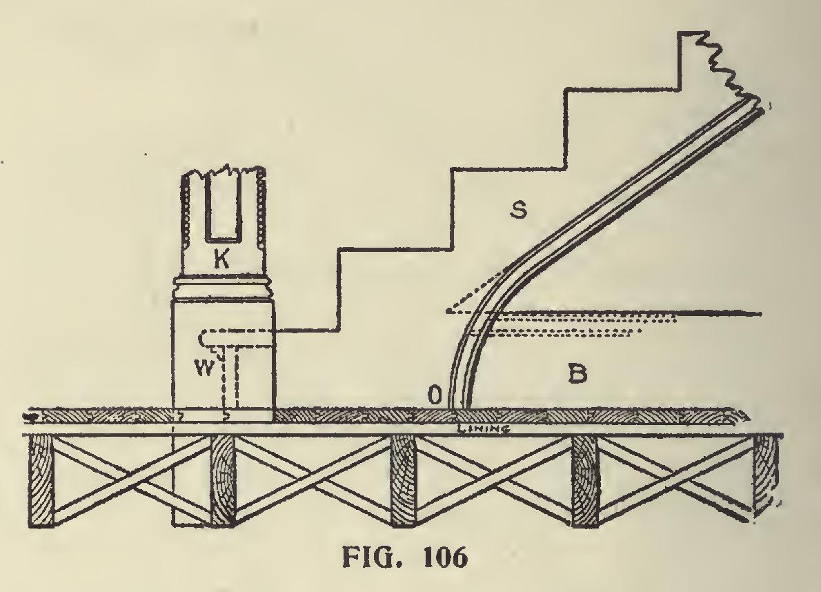
If there is a wall under the string S, then the base B, shown by the dotted lines, will finish against the strings, and it should have a mould ing stuck on its upper edge the same as the one on the lower edge of the string, if any, and this moulding should miter into the one on the string.
When there is a base, the piece 0 is dispensed with.
The square of the newel should run
down by the side of a joist, as shown, and be firmly secured to it by iron knees or other suitable devices. If the joist runs the other way, try and get the newel post against it, if possible, either by furring out the joist or cutting a portion off the thickness of the newel. The solidity of a stair, and the firmness of the rail, depend very much on the rigidity of the newel post.
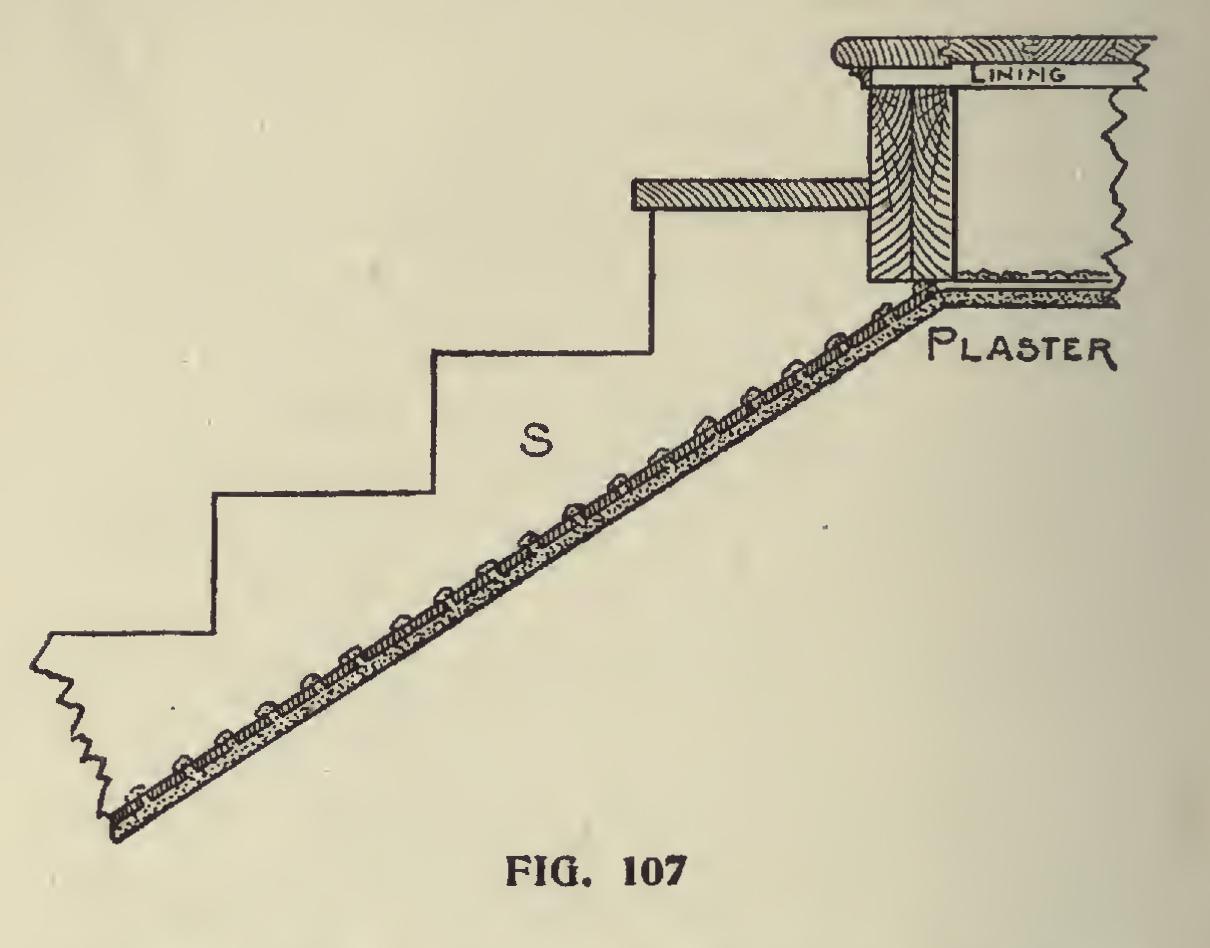
Fig. 107 shows how the cut string is finished at the top of the stairs. This illustration requires no explanation after the foregoing has been ex amined.
So far we have dealt with those stairs having a bevel at the bottom only; however, there are many modifications of straight and return stairs, that have either two, four or six newels. When any of those conditions arise, the treatment of strings at their finishing points will necessarily be somewhat different than that described, but the general principles, as shown and explained, will hold good. As this work is only intended to cover the simpler class of stair building, we will not enter into the more complicated phase of the work.
Miter Boxes.
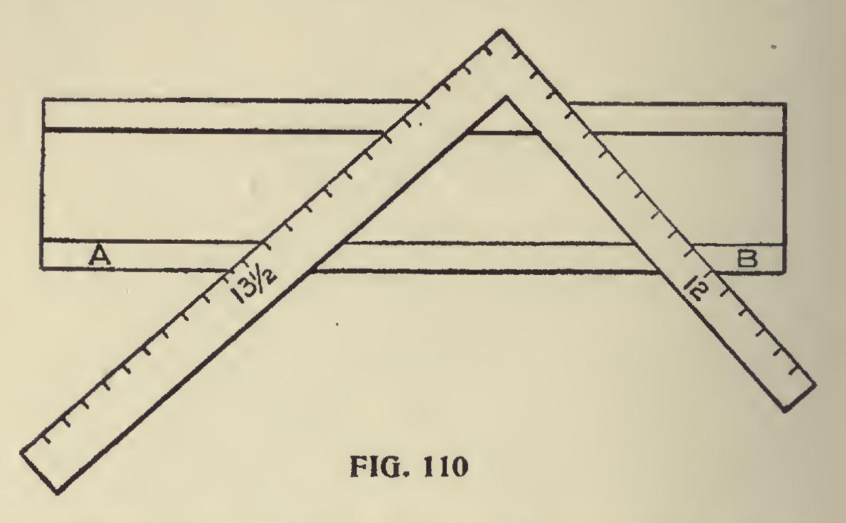
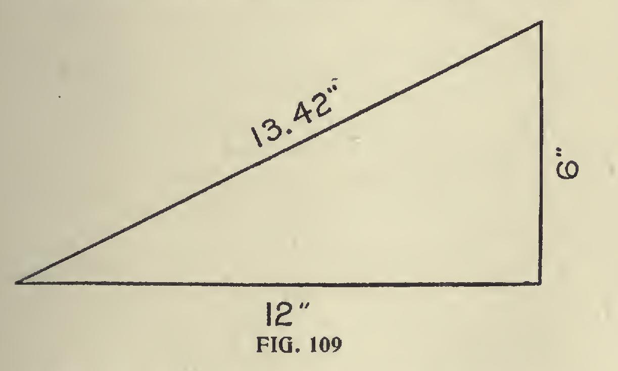
One of the most troublesome things the carpenter meets with is the cutting of a spring moulding when the horizontal portion has to miter with a gable or raking moulding. Undoubtedly the best way to make good work of these mouldings is to use a miter-box. To do this make the down cuts B, B (Fig. 108) the same pitch as the plumb cut on the rake. The over cuts 0, 0, 0, 0, should be obtained as follows: Suppose the roof to be a quarter pitch—though the rule works for any pitch when followed as here laid out—we set up one foot of the rafter, as at Fig. 109, raising it up 6 inches, which gives it an inclination of quarter pitch; then the diagonal will be nearly 13/ inches. Now draw a right angled triangle whose two sides forming the right angle, measure respectively 12 and 131 inches as shown in Fig. 110.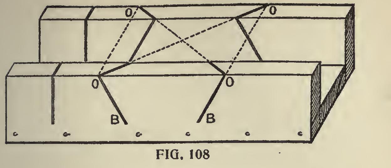
The lines A and B show the top of the miter box with the lines marked on. The side marked 131 inches is the side to mark from; this must be borne in mind, and it must be re membered that this bevel must be used for both cuts, the 12-inch side not being used at all.