Roughing-In
fig, pipe, sink, waste, shown, trap and floor
The plumber will find it a great help if he will jot down in a small memorandum book the roughing-in measurements of every fixture he installs, for this will save the trouble of looking up in the future when he may have fixtures of the same style to install. Let us examine the fixtures that go in on his job, and note the meas urements in our little book for future reference.

The wash trays—or laundry tubs, as they are sometimes called—are of the style shown in Fig.
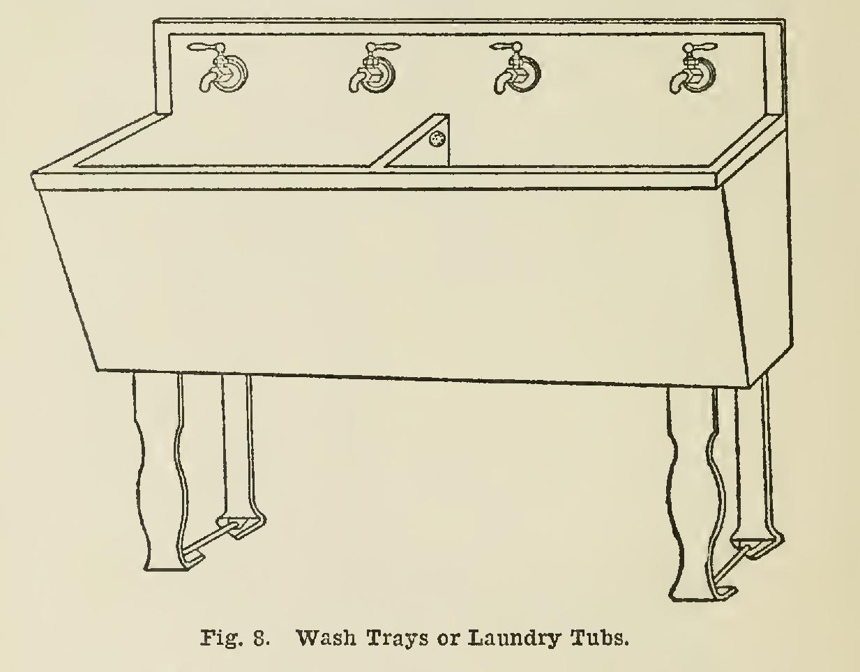
8, with rough brass continuous waste and trap as in Fig. 9; and are to be supplied with hot and cold water through Fuller bibbs, as shown in Fig. 8.
The floor drain is like that shown in Fig. 10. The kitchen sink is of the type illustrated in Fig. 11, with nickel-plated trap, with waste to floor and vent to wall, and nickel-plated Fuller bibbs.

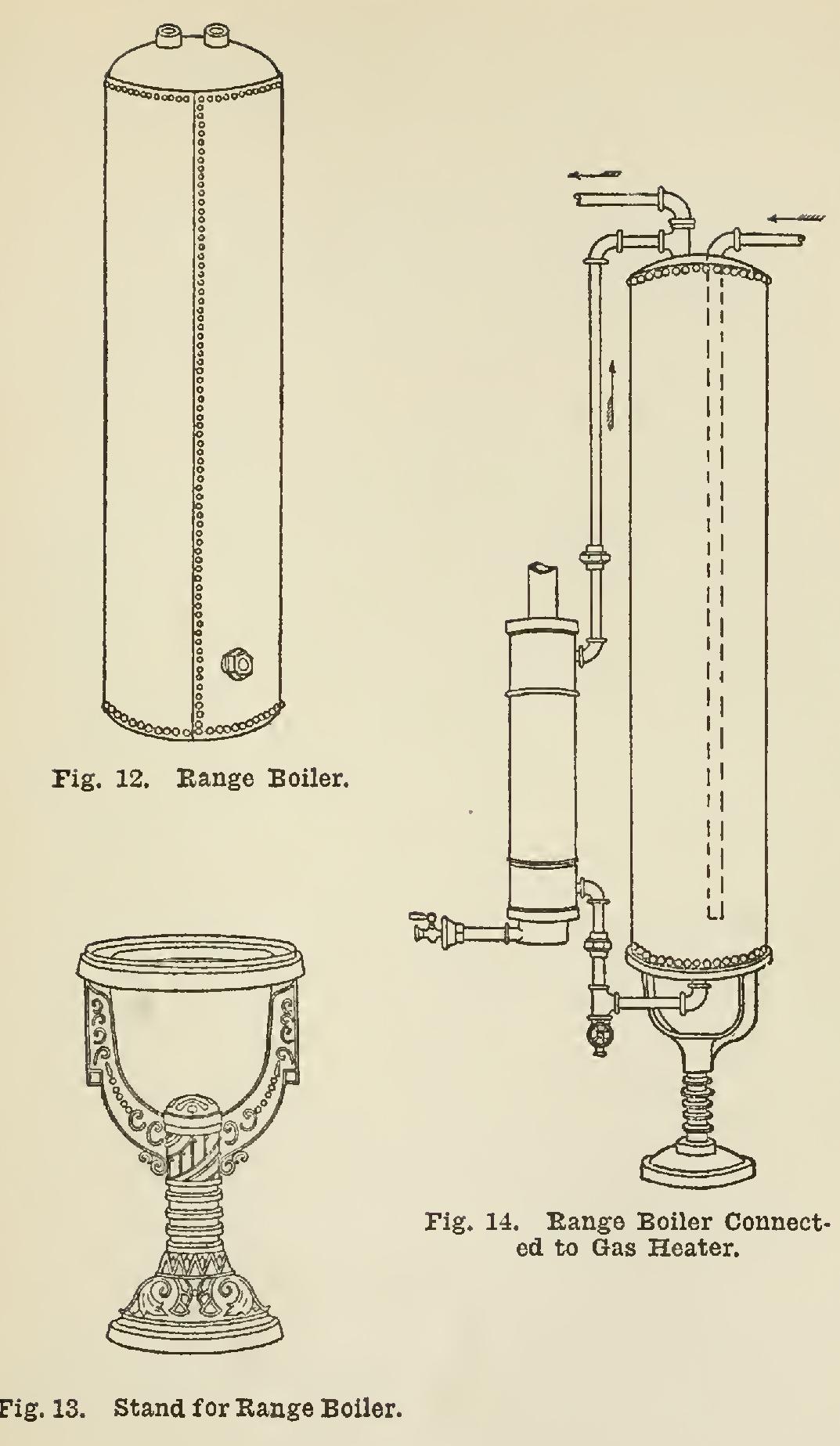
The range boiler is shown in Fig. 12. It is to be erected on a stand (Fig. 13), and connected to the kitchen range, and also to a gas heater as shown in Fig. 14.
The first-floor lavatory (Fig. 15) is fitted with nickel-plated Fuller basin corks, and nickel plated trap to wall.
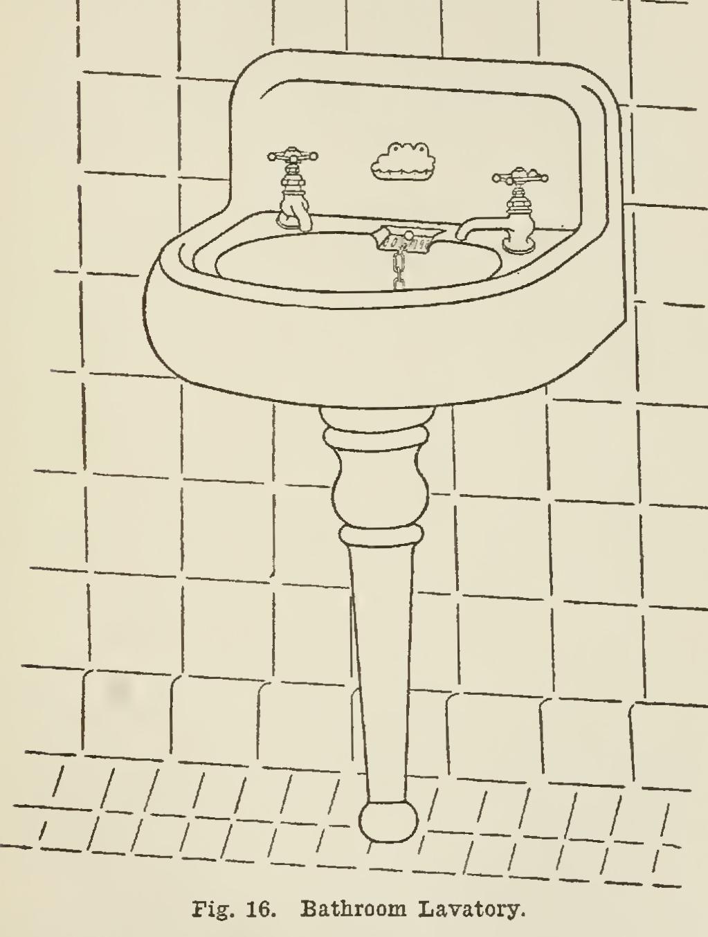
The lavatory in the bathroom (Fig. 16) is also fitted with nickel-plated Fuller corks, and nickel-plated trap to wall.
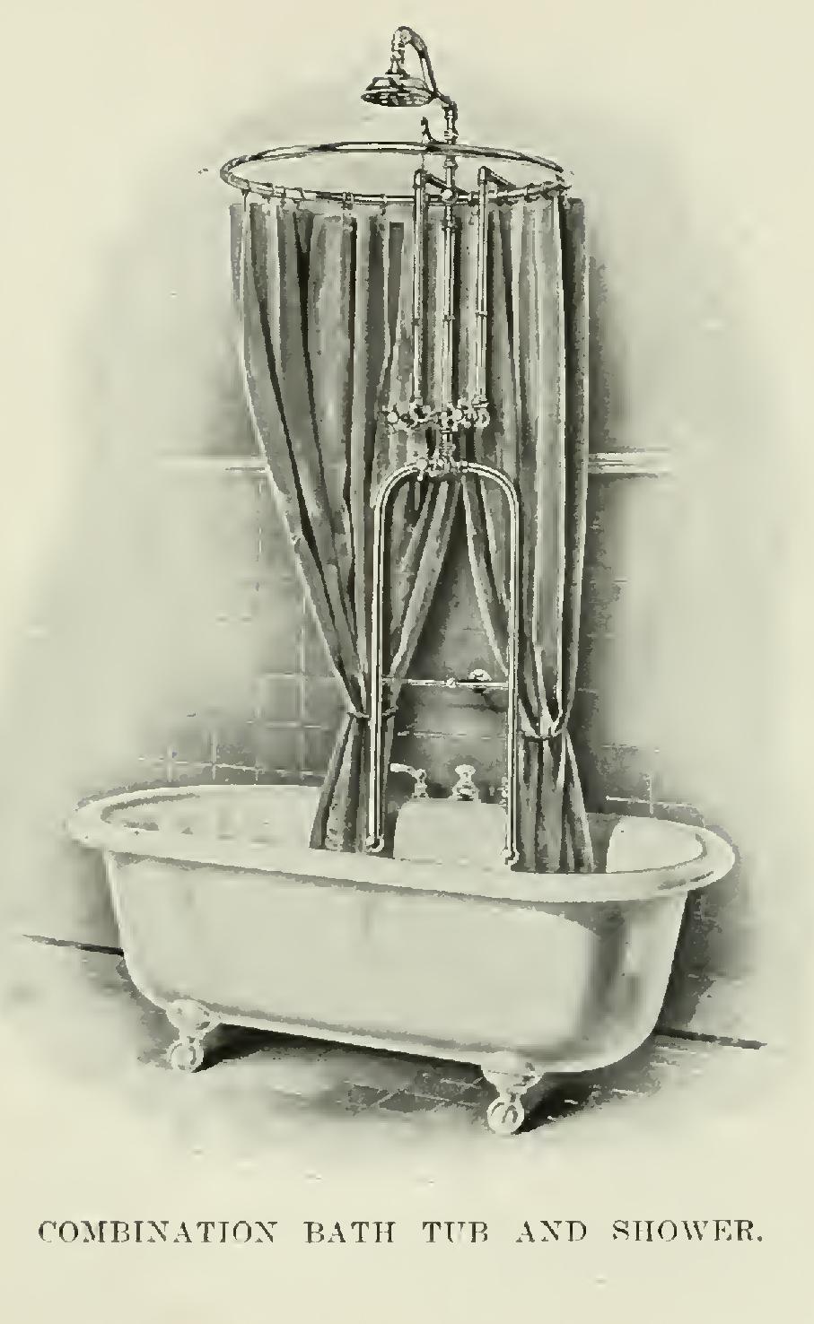
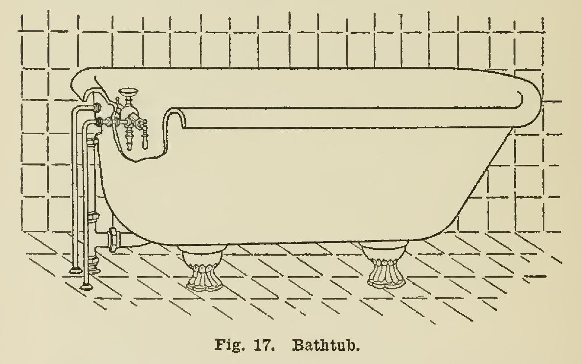
The bathtub is a five-foot tub of the type shown in Fig. 17.
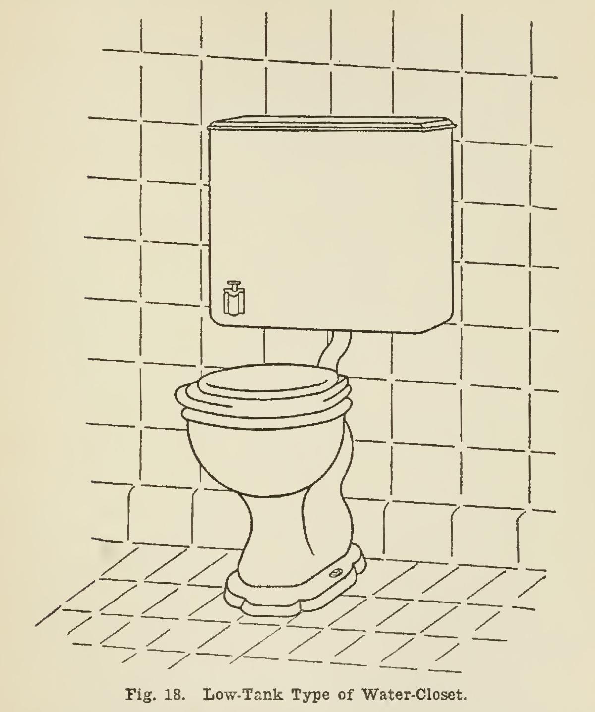
The closet is of the low-tank type illustrated in Fig. 18.
Having looked over the fixtures and noted the roughing-in measurements, we shall now start on the vertical pipe work.
Vertical Pipe Work.
Fig. 19 is an elevation of the sink and wash-tray stack, and we shall start to install this at once. Into the bend in the drain-pipe that is looking up, we first calk a 2-inch Y; and in the outlet of this Y we calk a 2-inch cleanout plug with brass cover and square head, for the purpose of clearing the pipe at any time a stoppage may occur. Continuing to the basement ceiling, we place a 2-inch Y for the sink waste. We shall probably have to use an offset here—that is, change direction and carry the piping along to where it will be in position to pass up directly through the first floor tition. Then, continuing upwards to a point about five feet above the first floor, we will place a 2-inch tapped tee, for the vents from the kitchen sink and the wash trays; and then con tinue on up to and through the roof, enlarging the pipe to four inches just below the roof, and placing a roof-flashing at the roof.

There are a number of different styles of roof-flashings, any one of which may be used, provided it will prevent the water from leaking through and provided it has good wearing quali ties. By enlarging the pipe to four inches where it goes through the roof, the danger of the pipe becoming closed with hoar frost is avoided. This same precaution applies to auy soil or vent stack carried through the roof.
The next step will be to get in the waste and vent pipes. For the sink waste we shall require a 2x11/2-inch brass ferrule, and about two feet of 11/2-inch lead pipe. After wiping the lead to the ferrule, we calk same into the Y left for that purpose, after bending the lead pipe to the proper place to receive the sink trap.
Into the tapped tee which was left for the vents, we screw a tee with nipple of right length, and drop out of the side opening to the basement for the wash trays, and out of the end opening to the sink. Here we shall need for the sink, and also for the trays, a female soldering nipple, and about 15 inches of lead pipe. After wiping the necessary joints, we screw the pieces onto the pipe, after bending the same to the proper angle. Then, closing the ends so that the job can be tested, we are through with this stack until time for setting the fixtures.
It will be seen that when we set these fix tures, it will be necessary to wipe a joint be tween the vent pipe now in, and the vent pipe from the traps, and this connection will leave plenty of "spring" in the piping for expansion and contraction. In some localities the connec tion between the vents in the wall and the trap vents is made by means of slip joints, with a rubber gasket to make the joint tight and allow for expansion and contraction. Various authori ties differ on this subject, so that we shall not argue over this point, but will take up the work on the wash tray waste, which will require to be of the same style as the waste for the sink, and the end brought through the basement floor for future connection.