Steam Heating
boiler, condensation, fig, branches, return, connection and pipe
For economy, choose a boiler so constructed that it may be easily and thoroughly cleaned in all its parts. Soot is a great non-conductor; and the heating surfaces, to be effective, must be kept free from an accumulation of it.
The firebox and grate provided are features worthy of particular attention, as a firebox of proper depth, and a type of grate which can be easily cleaned and which is able to carry its full load of fuel without a sagging of the bars, are essential points to consider.
A large amount of direct heating surface above the grate, with a length of fire travel suffi dent to cons 'me and utilize the gases of com bustion, means economy of fuel.
Cast-iron boilers are used to a greater extent than wrought-iron constructions for low pressure heating purposes, as experience has conclusively demonstrated that cast iron is slow to corrode or rust, is easily moulded into any desired shape, and is most efficient in absorbing the heat units from fuel consumed.
Do not select a boiler having packed joints, as it will dry out and leak at these points. Iron to iron connections made with push or screw nipples are the best.
Finally, select a boiler made by a company or firm of unquestioned business standing. Such a concern will make good any defects of manu facture which may develop in their product and for which they can be considered responsible.
One-Pipe Circuit System. The one-pipe cir cuit system of steam piping is doubtless used more than any other plan, as it is the one having the most advantages when installed in a square or rectangular building.
In this system, the upright pipe out of the boiler rises to as high a point as possible, up to within a few inches of the cellar joists. On its top is placed an elbow from which the circuit is started. This starting place is the high point of the main steam pipe; and from it the main should have a gradual fall or pitch from the boiler of one-half inch to one inch in each ten feet of length. The branches should pitch up from main at least one inch in each five feet of length, and as a rule should be of one size larger pipe than are the risers which they feed.
The circuit continues around the basement at a distance of from three to four feet from the outside wall, continuing until an advisable point at or near the boiler is reached, where a reducing elbow is placed on the end of this main, and a drop made with a smaller size of pipe into the return opening of the boiler.

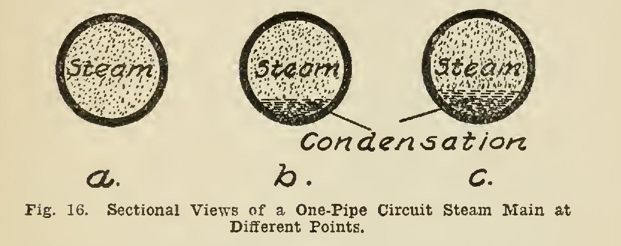
Fig. 15 shows the basement plan of a piping job of this character. The main acts as a reser voir supplying the various branches leading to the radiators, and also as a return pipe receiving the condensation from the various branches it feeds. By reason of this latter function, it should not be reduced, but should be run full size from the boiler to the end where the return connection is made. The condensation from the system runs along the bottom of the main in the same direction as the course of the steam. Fig. 16 illustrates three views of a main of this character, showing the extent of the reduction in its area due to the space occupied by the con densation; a designates the main as it leaves the boiler; b, the same main after the condensation from several branches has been returned to it; and c, this main at a point near to the return connection, showing possibly one-quarter of its area occupied by the condensation.
At the extreme end of the main, where the connection to the return is made, there should be placed an automatic air-valve, in order that all air in the main may be quickly exhausted, and the main put in shape to be rapidly filled with steam so that all branches will be supplied at practically the same time, thereby securing an equal proportion of heat from all radiators.
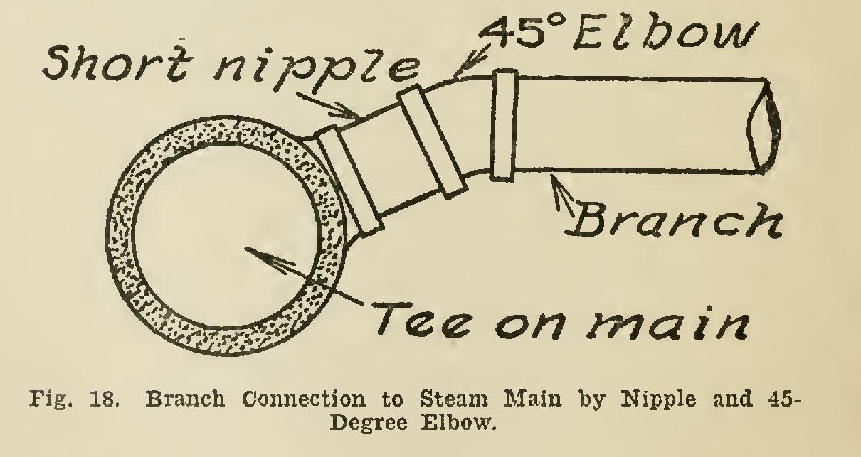
Each branch connection may be taken from the main by either of two methods—namely, (1) by using a nipple and 90-degree elbow, as illustrated in Fig. 17; and (2) by using a nipple and 45-degree elbow, as illustrated in Fig. 18.
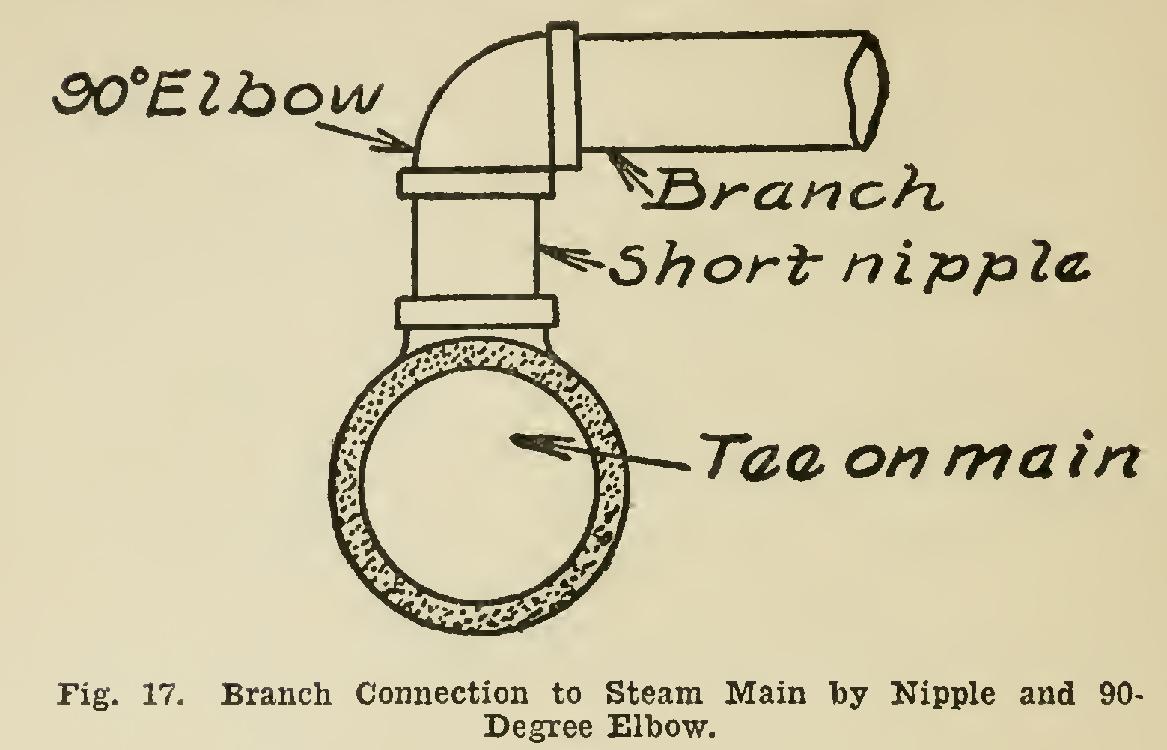
The method shown in Fig. 18 is preferred for the reason that in all low-pressure mains the steam flows along the top, the condensation along the bottom. With the 45-degree connec tion. the condensation each branch enters the main without saturating the steam, while with the use of the 90-degree connection this water of condensation flows into the main on top of the steam supply, saturating it and thereby greatly reducing its efficiency. This dif ference is very clearly explained by Fig. 19.