Steam Heating
return, boiler, system, pipe, elbow, connection, fig and one-pipe
Points marked A A A on Fig. 15 indicate the 45-degree connection; B B B, the risers to radi ators; and C the point at which the automatic air-valve should be placed. The arrows indicate the downward pitch of the main and the upward pitch of the branches.

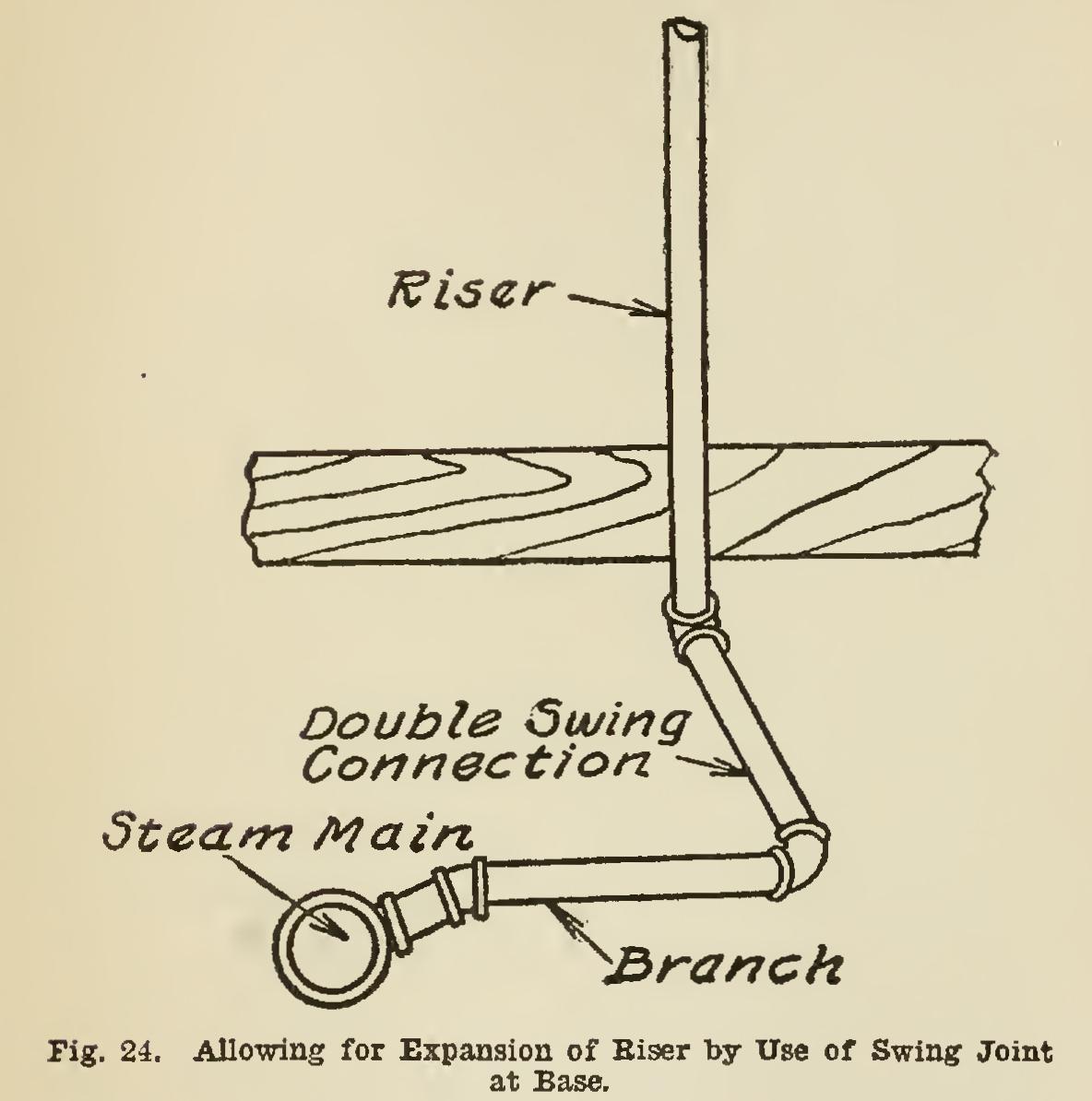
On all low-pressure steam work, the velocity of the steam through the riser out of the boiler should be materially less than that provided in the main. To accomplish this result, it is well to have the riser of one or two sizes larger pipe than that used for the main, placing a reducing elbow at the top to start the main.
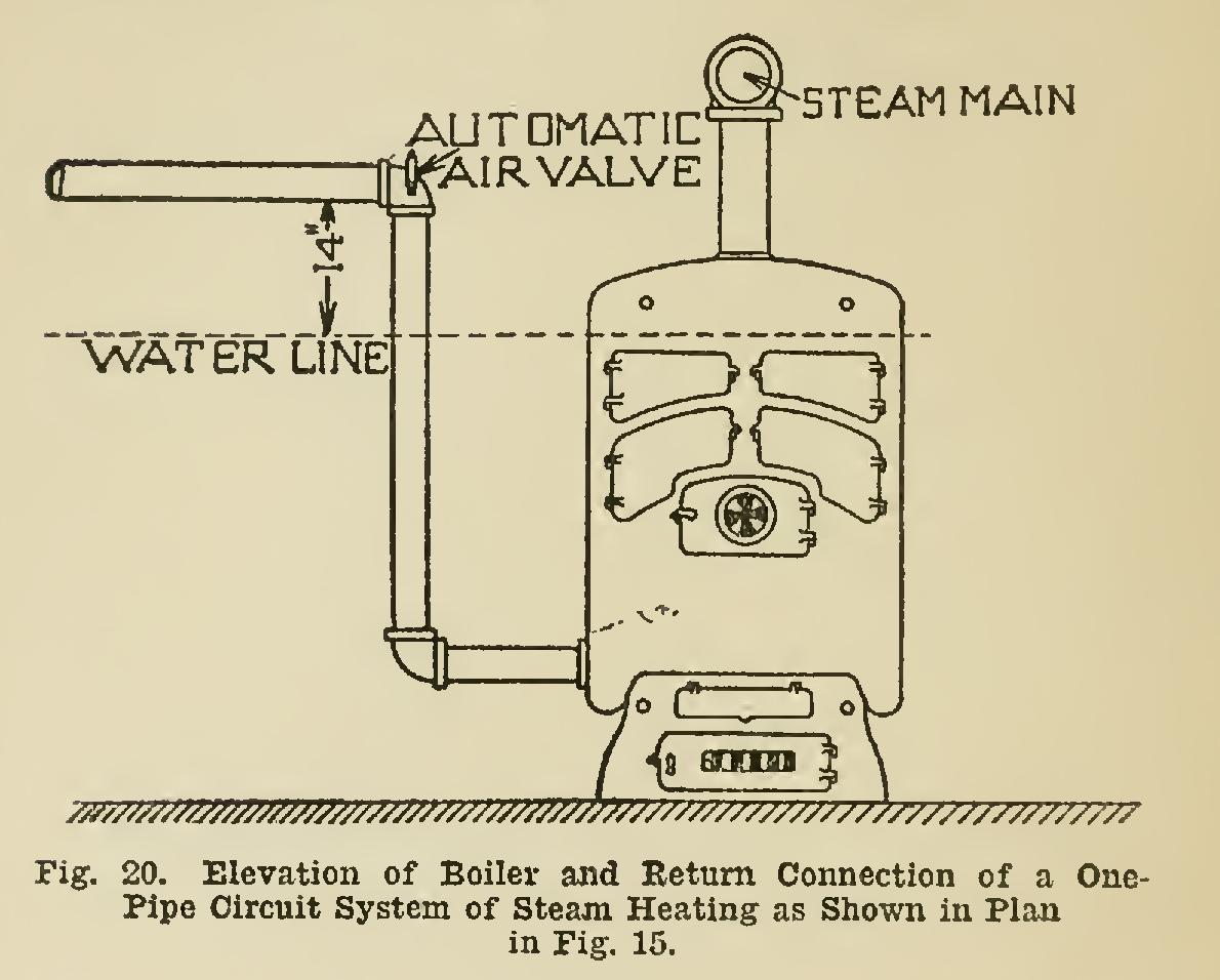
The end of the steam main should never be lower than a point 14 inches above the water line of the boiler; and, if possible, a distance of 20 inches should be maintained between the two points. Fig. 20 shows an elevation of the boiler and return connection of a piping system as shown in plan in Fig. 15, and clearly indicates the space to be maintained between the end of the main and the water-line of the boiler.
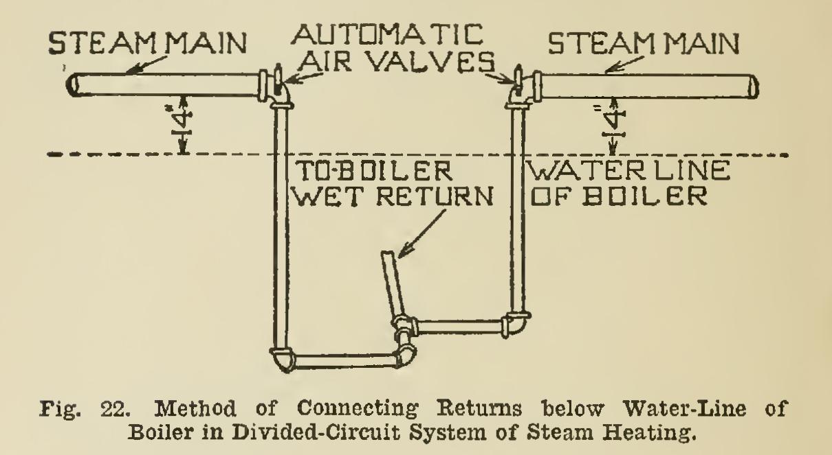
Divided-Circuit System. The divided-circuit or two-circuit system is quite similar in its gen eral plan to the single-circuit, and what has been said regarding the details entering into the one will apply to the other. When the boiler is located on one side of a rectangular building, frequently it is better practice to run the main in two circuits; and the method this provides is known as the divided-circuit system. On leaving the boiler, the mains pitch down from it in either direction, following around the base ment until they meet at the side opposite to the boiler, or perhaps at some other point, the place of junction depending upon the character of the building or on circumstances surrounding the installation. At this point a reducing elbow and an automatic air-valve are placed on the end of each main, and a drop made to the floor of the basement, where, below the water-line, these returns are connected together, and a single pipe having a capacity equal to that of both the drop pipes is run across the cellar floor, either on the surface or under it, to the boiler, where it is con nected into the return opening.
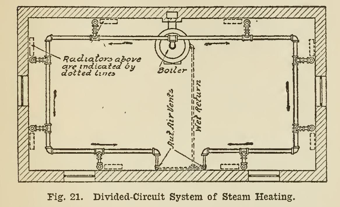
As the ends of the mains or circuits are usually some distance from the wall, it is not advisable to drop directly at this point, but preferable rather to carry the pipe to the wall, and then drop.
Fig. 21 illustrates the divided-circuit system; and Fig. 22, the method of connecting the re turns together below the water-line of the boiler.
One distinct advantage of a one-pipe circuit system is that all piping is overhead and out of the way. In addition it affords a very neat and attractive method of piping, and will be found sufficiently effective provided care is exercised in properly proportioning the sizes of the pipes.
Pipe sizes for one-pipe systems are given iu Table II.
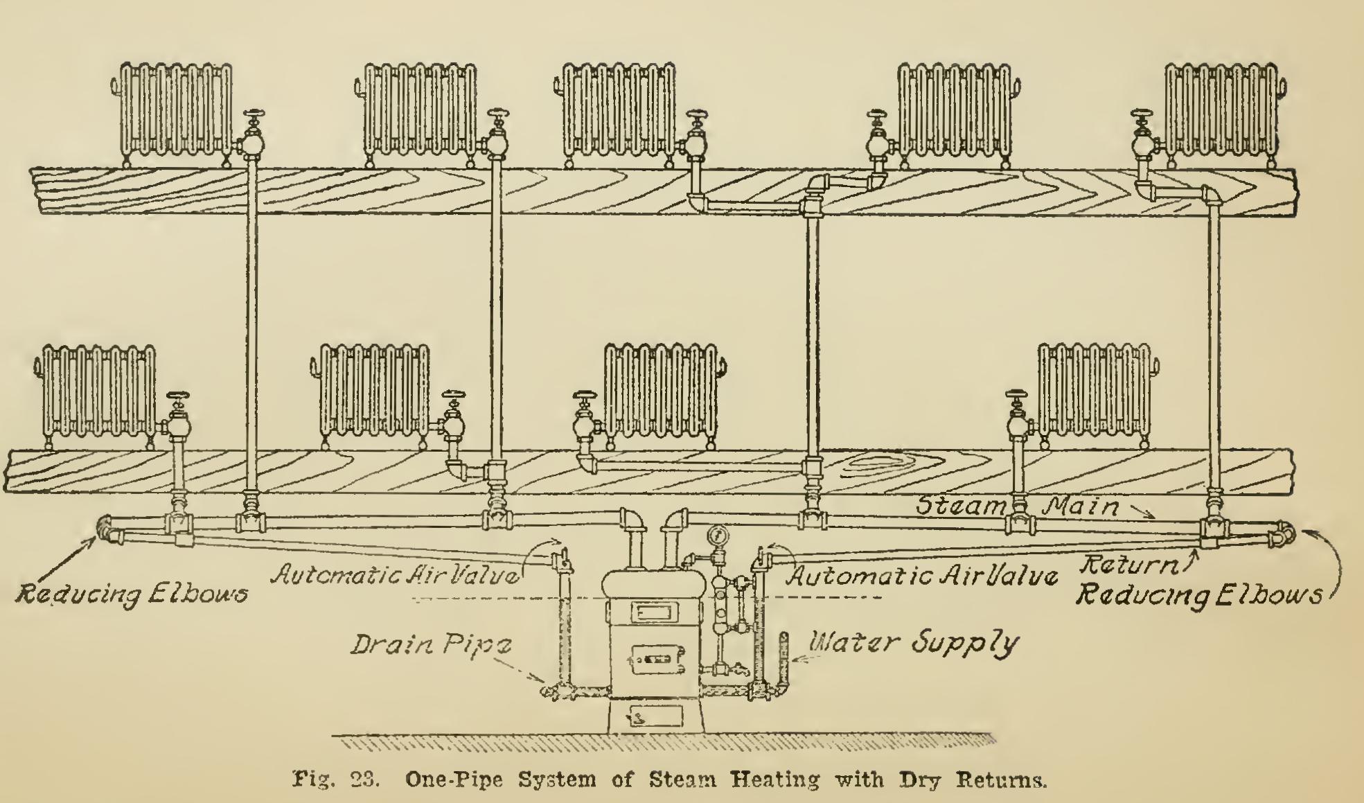
One-Pipe System with Dry Returns. The one-pipe system of steam heating is so called from the fact that there is but one pipe connec tion to each radiator, this pipe acting the dual role of flow and return. For this reason the use of this arrangement requires pipes larger in size than those necessary for the two-pipe system. There are several adaptations of the one-pipe method, that illustrated in Fig. 23 being the one particularly suited to a long narrow building where the main flow pipes may be run straight from the boiler in either direction.
The high points of the steam main are the elbows on the risers leading from the boiler, and from this point the mains and returns should have a gradual fall, free from pockets and traps, toward the return opening of the boiler, this fall or pitch averaging not less than one-half inch for each ten feet of length of the flow or return. Unless the system is modified to meet certain unusual conditions, such as an uneven height of the basement ceiling or similar oddities in con struction, there should be no reduction in the size of the main prior to making the connection to the return.
Note the manner in which this connection is made. The return pipe is always one or two sizes smaller than the flow, and the connection from main to return is accordingly made with two reducing elbows and a close nipple. Assum ing the main to be 3 inches and the return inches in size; on the end of the main is placed a 3x2-inch elbow, into which is screwed a 2-inch close nipple. To the other end of the nipple is attached a 2x11/2-inch elbow, into which the return is connected. Note two things particularly, relative to this form of connection —first, that the 3x2-inch elbow is turned up until the top side of the elbow is even with the bottom of the former size. This method assists in gaining headroom in the basement, at the same time permitting of the perfect drain age of the condensation from the main. Second, note that, should a length of pipe for the return be screwed directly into the reducing elbow, it would extend out at a considerable angle from the main; and as it is desirable for the return to follow closely by the side of the main and just beneath it, it is necessary to use a short piece of pipe and a coupling with a crooked thread to throw the return straight with the main.