Intersection and Development 75
plane, cylinder, true, curve, base, shown, plan and elements
88. In Fig. 70 are shown the same cone and the same cutting plane Y; but the curve is found without the use of any but the two outside or contour elements 0-1 and 0-7. The highest point c is first determined as in Fig. 68. Other planes between Z and the base are then taken. Let W be one such plane. Plane W cuts a circle from the cone, the diameter of which is x-y. A circle with this diameter may then be drawn in plan, intersecting plane Y in points b and d. These points are in plane W, and hence are located in elevation by projecting from the plan to plane W. Points on U and on as many other planes as may be chosen, are obtained in the same way.

Very often this method of construction is better than that of Fig. 68, on the score of accu-. racy. By referring to Fig. 68, it will be seen that, owing to the steep inclination of elements 0-3 and 0-5, when b and d are projected from the plan, their exact position on 0-3 and 0-5 is a matter of some uncertainty.
89. Auxiliary Planes. Planes such as Z, W, and U, in the last three figures, introduced to work out or facilitate some part of the solution, are called auxiliary planes.
90. Still another form of curve results when, as in Fig. 71, the cutting plane is taken parallel to one element. The plane X, perpendicular to V, is parallel to the element 0-1. The plan of the intersection is found by the method of Fig. 70. The curve in this case is a parabola, in accordance with the definition of geometry, that "the curve cut from a cone by a plane which is parallel to one and only one element is called a parabola." The true size of the section may be found by a simple construction. The curve is evi dently symmetrical with respect to a line d-z, which is the axis of the curve and is represented in its true length in elevation. If, now, a view of the curve be taken in the direction of the arrow, the true size and shape will appear. The actual distance between points c and e, for example—that is, the true width of the curve at that part—is shown in plan as the length c-e. The true widths b-f and a-g are similarly shown. It will be seen, then, that while in plan the true width of the curve at any part is shown, the real distances along the axis d-z are not there shown. For example, the distance from d to line c-e is not a true length. But these dis tances along the axis are shown true length in elevation, from d to c-e, d to b-f, etc.
Hence, to show the true size of the curve as seen in the direction of the arrow, all that is necessary is to combine the true lengths of the elevation with the true widths of the plan.
Therefore, at any convenient distance, draw m-n parallel to d-z; project with the triangles from c, e, b, f, etc., at right angles to m-n; and make the widths and equal respectively to c-e, b-f, and a-g, half of each on either side of the axis m-n.
Intersection of a Plane with a Cylinder 91. A right circular cylinder standing on its base and cut by a plane X perpendicular to V, is drawn in Fig. 72. The development of the cylinder is also shown. As in the ease of the plane cutting the cone, elements of the cylinder are drawn, and the points noted in which the plane cuts the elements. The base is here divided into twelve equal parts, and twelve ele ments drawn. The plan of the intersection will coincide with the plan of the cylinder, since the whole convex surface is projected in the circle.
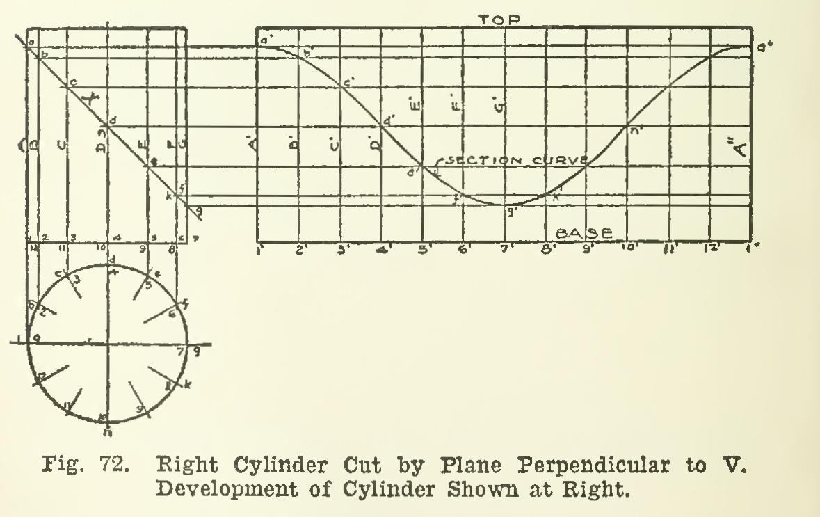
Development of the Cylinder and of the Curve of Intersection. Let the cylinder be placed with point 1 of the base at point 1', and element A at A', on the plane of the paper. Now imagine the cylinder rolled on the paper until the entire curved surface has come into contact with the paper, and element A is again on the paper at A", parallel to A'. The distance between A' and A" is therefore the shortest dis tance around the cylinder as measured around the base.
As the cylinder rolls from A' to A", the base remains always in a plane perpendicular to the elements, and hence perpendicular to the plane of the paper. Therefore, as the cylinder is developed, the edge of the base rolls out in the straight line drawn from 1' perpendicular to A' and extending to A". The approximate dis tance around the base is laid off in the develop ment, by taking the chord of one of the equal divisions of the base, and spacing it twelve times along 1'-1", locating the points 2', 3',...6'. . .1". Lines drawn through these points at right angles to the developed base, will be the devel oped positions of the numbered elements. The lengths of the elements are taken directly from the elevation, since the true lengths are there shown; and a straight line through the upper ends of the elements will be the development of the top of the cylinder. The development of the curved surface of the cylinder is therefore the rectangle as shown.