Intersection and Development 75
moulding, x-y, plane, drawn and true
If plane Z represents the plane of the end of the house, then the edge of the moulding drawn through d is in this plane; and the other points of the cross-section, m, p, q, stand out from this plane the distances which are shown in plan from mh to Z, from qh to Z, etc. Hence, if plane X-Y be revolved about an axis in plane Z, the distances from Z, as mh-5, nh-6, and so on, will revolve at right angles to X-Y; and when the plane of the section coin cides with Z, the distances will show on V in their true lengths at m∞-m', n∞-n', etc. This process worked out for each point will give n', m', p'....t∞ as points on the outline of the section as seen lying on V, and hence shown in its true size and shape. The back edge n'-s∞ may be drawn at any convenient angle. The figure n', m'...r'...t∞ is therefore the required cross-section.
If, in a problem like this one, the miter is at the usual angle of 45 degrees, there is a very short construction as follows: Let the horizon tals cv-11, Y-12, 2v-13, and 3r-14 be drawn. The line 1∞-12, for example, is equal to 1''-15'; and, as the miter is 45 degrees, lh-15h is equal to cP-15h; that is, 1v-12 is equal to clh-15h. Hence, if the distance lv-12 is taken and laid off from q∞ at right angles to X-Y, the point q' on the true size will be determined.
In the same way, it may be seen that b'-10 is equal to mv-m'; 2v-13 to rv-r', and so on. Hence the short construction for finding the true cross-section is to draw the horizontals br-10... r-12.. .3v-14, and lay off these distances from X-Y as shown.
To Construct the Development of a Sheet-Metal Moulding Fig. 76B shows a moulding mitered at both ends. The elevation is given complete, and the
x plan shows the miter at the left end. The sur face of the moulding is partly curved, and partly plane. To make the development, proceed according to the principles of the development of a cylinder, under Article 91.

Since the moulding is symmetrical at both ends, a center line X-Y, from which to take measurements, is drawn in elevation. The given moulding miters with two others at right angles to it on miter planes at 45 degrees; hence the three mouldings are alike in cross-section. The curved outline at either end of the given mould ing must represent the true shape or end view of the other moulding, as each other moulding is perpendicular to the given one. The curved outline at either end is then also the true cross section of the given moulding, and the width of the developed moulding will be equal to the length of the line a, b, . . . e, . . .k.
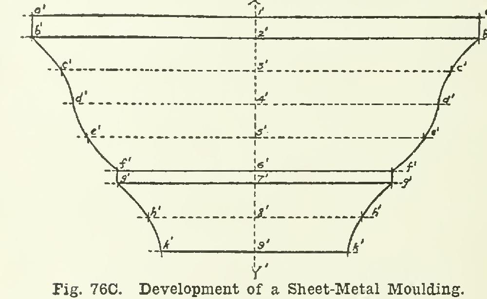
The development is drawn in Fig. 76C, where X'-Y' represents the position of X-Y, and the width 1'. . . .9' is equal to the length a, b, . . . e . . . k. The lines d-d, and h-h are lines drawn on the curved suriace in order to get the development.
The distances a-b, b-c, c-d, d-e, and so on, to the point k, are then laid off along X'-Y', giving the points 1', 2',...5',...9'; and through these points, lines are drawn indefinite in length and perpendicular to On these lines, the half-lengths 1-a, 2-b, etc., taken from Fig. 76B, are laid off, locating the points a'a', b'b', c'c', up to k'k'. These points, when joined, give the ends of the required development.