Miscellaneous Framing
chamber, roof, ice, boarding, laid, studs, planed, inches, food and matched
The partition between the ice and food cham bers next requires attention. It is formed of 2-by-6 studs laid on a 2-by-6 shoe piece spiked on top of the first layer of 2-by-3 bearers in the ice chamber. These studs must be planed on all sides, as they form the sides of the flues for the passage of the warm air from the refrigerator to the ice. A layer of planed matched boarding, laid horizontally, is then nailed to the studs, followed by a layer of paper and another layer of planed u matched boarding, laid vertically. These layers of boarding are stopped 10 inches from the ceiling of the ice chamber to form the outlet for the warm-air flues.
The end wall of the ice chamber, above the food chamber, must now be formed. First spike some planed pieces of 2-by-4 to the 2-by-6 studs just described, and to the 2-by-8 studs at the outer end of the food chamber, to form joists. The under side of these 2-by-4 joists is covered with planed matched boarding, all except a space of 12 inches at each end.
Short pieces of planed 2-by-4 are then spiked against the edges of the 2-by-6 studs to piece out the flues to 10 inches wide. Upon their edges are laid two layers of boarding with two layers of paper, and battens between. Next, 2-by-8 studs, resting on 2-by-8 pieces, supported on the 2-by-4 longitudinal ceiling joists, are fixed in position; and these are in turn covered with 2-by-2 strapping, vertical boarding, and battens, as before described for the outside finish.
The spaces between the 2-by-8 studs and 2-inch strapping are packed with sawdust, as before specified.
The ceiling proper of the refrigerating cham ber is then formed of 2-by-4 joists, with matched boarding on the under side and a 15-inch layer of sawdust on top.
The ice chamber end of the building has a small door in the gable to afford means of access to the space over the ceilings, so as to allow of the sawdust being packed down and added to from time to time. There is also a door below which gives access to the ice-chamber and is built in three pieces for convenience in charging. The doors are of 1-inch matched boarding on the face and of the same material, laid diagonally, on the inside; stout building paper is laid between the two layers of boarding. Wide rab bets or stops should be formed, and rubber draught-stop tubing nailed on them, so that the doors close tightly against it.

The other end of the building, as shown in the elevation (Fig. 273), has a door in the gable similar to that in the ice-chamber end; but, as may be seen from the plan (Fig. 272), the door to the refrigerating chamber is double, with an air-space between. Each door is constructed in the manner described for the ice-chamber doors. A good birch or oak sill should be pro vided.
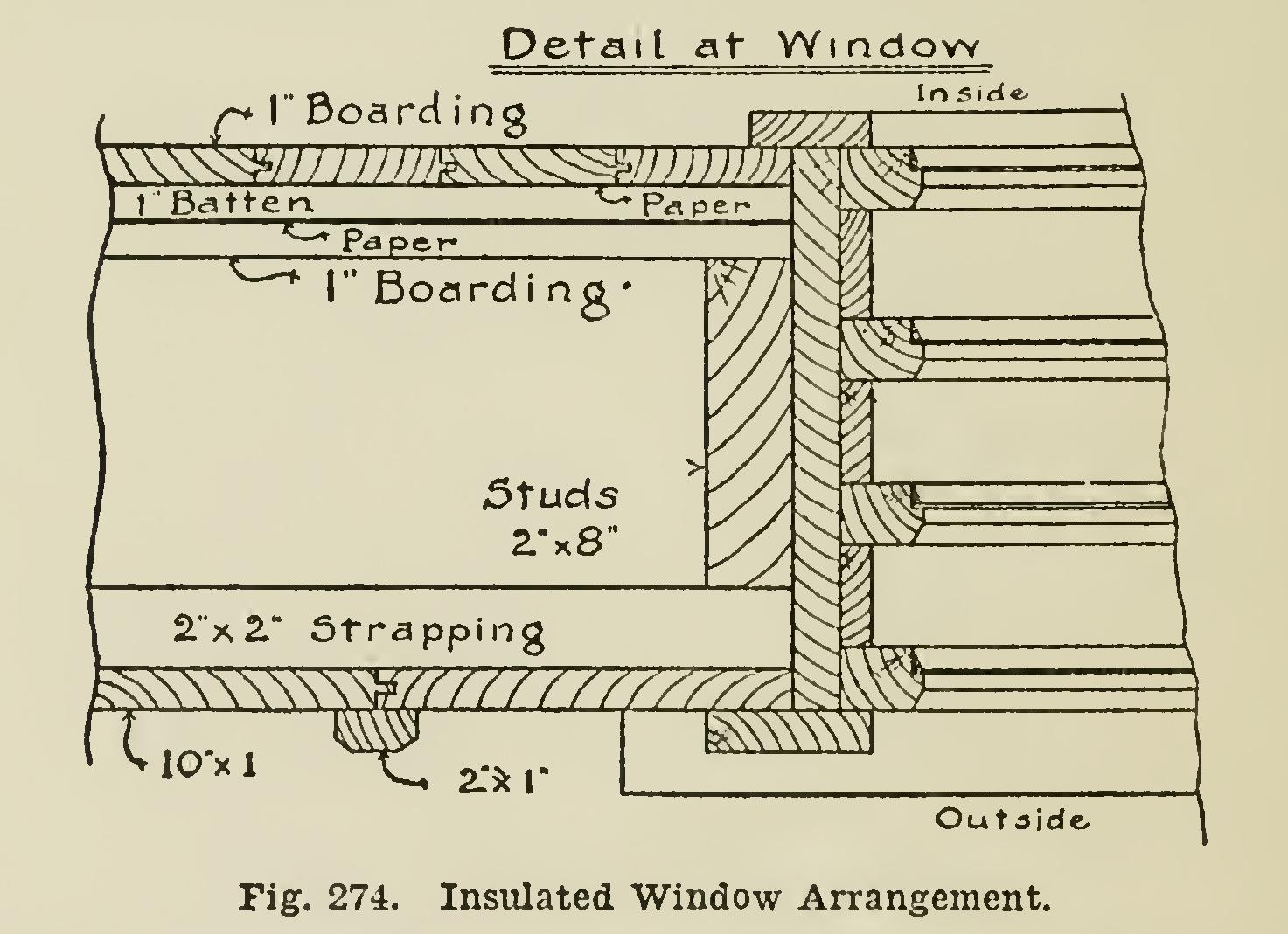
The windows in the refrigerator chamber are quadruple (see Fig. 274). Each of the four sashes is fitted closely into the frame, and held in place with stops, as shown in detail. The window frame is of stout 1-inch stuff, and the sill is 2-inch. Great care must be taken in making the window-frame, so that no leaks can occur. This is important, for the efficiency of the whole plant depends upon every part being as far as possible air-tight, so that the condition of the atmosphere outside shall not interfere with the circulation in the interior.
When food is placed in the refrigerating chamber (on suitable shelves, hooks, etc.), the warm air rises from it and passes through the flues into the ice chamber. There it comes in contact with the ice, and passes down at the sides and end, through the cold-air flues under the floor, and into the food chamber again. This process continues indefinitely, hut of course becomes slower when the contents of the refrig erator chamber are thoroughly chilled.
The drain is also an important part and must be carefully constructed, or it may afford a means of entrance for warm air from without. The drain inside the chamber is of wood, lined with heavy galvanized iron, and should dis charge into a terra-cotta gutter trap, connected with a few feet of pipe to carry the drainage clear of the site. The banking of the building with earth for a height of 12 or 15 inches is another precaution.
The inside of the ice chamber is left rough. The food chamber must have two or three coats of good shellac varnish, and the whole of the exterior should be painted in the usual manner.
The size of house here described is the smallest recommended, but no difficulty will be found in adapting the methods and specifica tions to larger houses.
Summer House or Band Stand.
A very neat and pretty roof may be made by using rafters with an even curve. The rafters may be cut out very quickly and cheaply by doing the saw ing with a band-saw in the shop.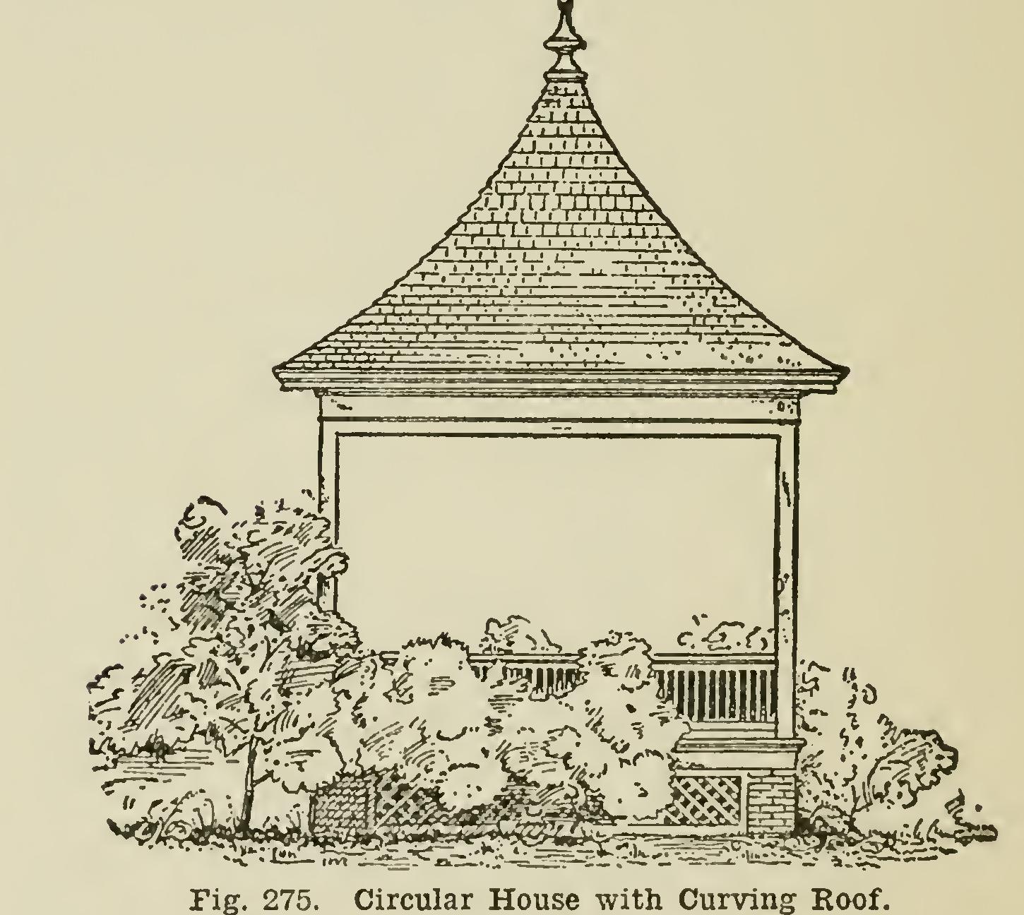
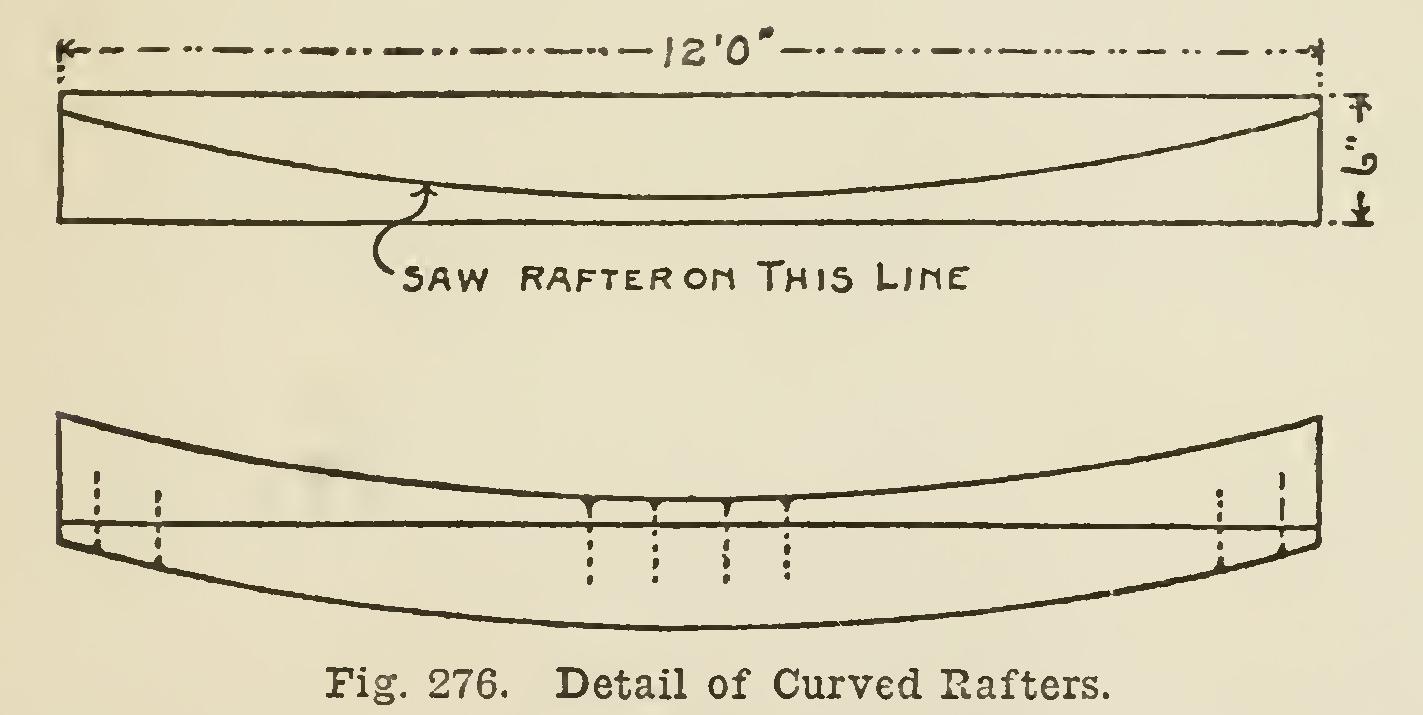
First make the pattern the curve and length needed, by describing a section of a circle having the proper radius to cut within an inch or half inch of the top and bottom edges of the rafter as shown in the detail drawing, Fig. 276. To make the radius, use tram points, if you can get a bar long enough; but a light wire will probably be better, because the length in some cases will be twenty or thirty feet. There is too much stretch to a chalk line.
There is no waste of material in cutting rafters in this way, except the saw cut; and there is no more work than is necessary on a straight roof, except in cutting the roof boards and shingles at the hips.
The roof looks better when the shingles are laid with increasing weather exposure for each course, commencing at the eaves with three or four inches, according to the length of roof, and increasing the weather surface each time until it is six or seven inches at the peak. The gradually increasing spacing apparently adds to the curve of the roof; and this gives the roof an interesting appearance.
Where a curve of this kind is used on two sides of a building with gable ends, the increased cost is very slight, because the curve is not suffi cient to interfere with laying the shingles easily, and the roof boards go ola just the same as on a straight roof. Where the pitch is sufficient, and you do not care for the graduated effect, the shingles are laid in the usual way.