Pitches and Roof Framing
hip, rafter, shown, common, cut, cuts, square, angle, line and run
In Fig. 235, we show how all of the lengths, cuts and bevels may be obtained from the tri angle, bounded by A-B-C, formed by the runs of the common and hip rafters and the tangent, as shown at No. 1, as follows: From the run of the common rafter, erect the desired rise as at A-D and connect D-B. This forms the second triangle and contains the length, seat and plumb cuts of the common rafter, as shown in No. 2. At right angles from the common rafter draw a line equal to the tangent as and connect D-C'. This forms the third triangle, as shown in No. 3. In this are shown the face cut of the roof boards to fit in the valley or over the hip. This angle also gives the cut across the back of the jack to fit against the hip or valley, commonly called side cut of the jack. At right angles from the com mon rafter draw a line equal to the rise as D-A' and connect This forms the fourth triangle, as shown in No. 4. In this is shown the edge or miter cut of the roof boards to fit in the valley or over the hip. In other words, this is the same as the miter for a hopper. Now then, we will work from the other side of triangle No. 1. From the run of the hip draw a line at right angles from A-C equal to the rise, as at A-D' and connect C-D'. This forms triangle No. 5, and contains the length, seat and plumb cuts of the hip. From hip rafter and at right angles to A-C draw a line equal to as C-E and connect A-E. This forms triangle No. 6 and in it is contained the top or, commonly called, the side cut of the hip. The illustration. is for the 3-8 pitch or 9 inches rise to one foot run of the common rafter. For an octagon roof the angle at No. 1 would be 221 degrees. For a hexa gon roof it would be at 30 degrees.

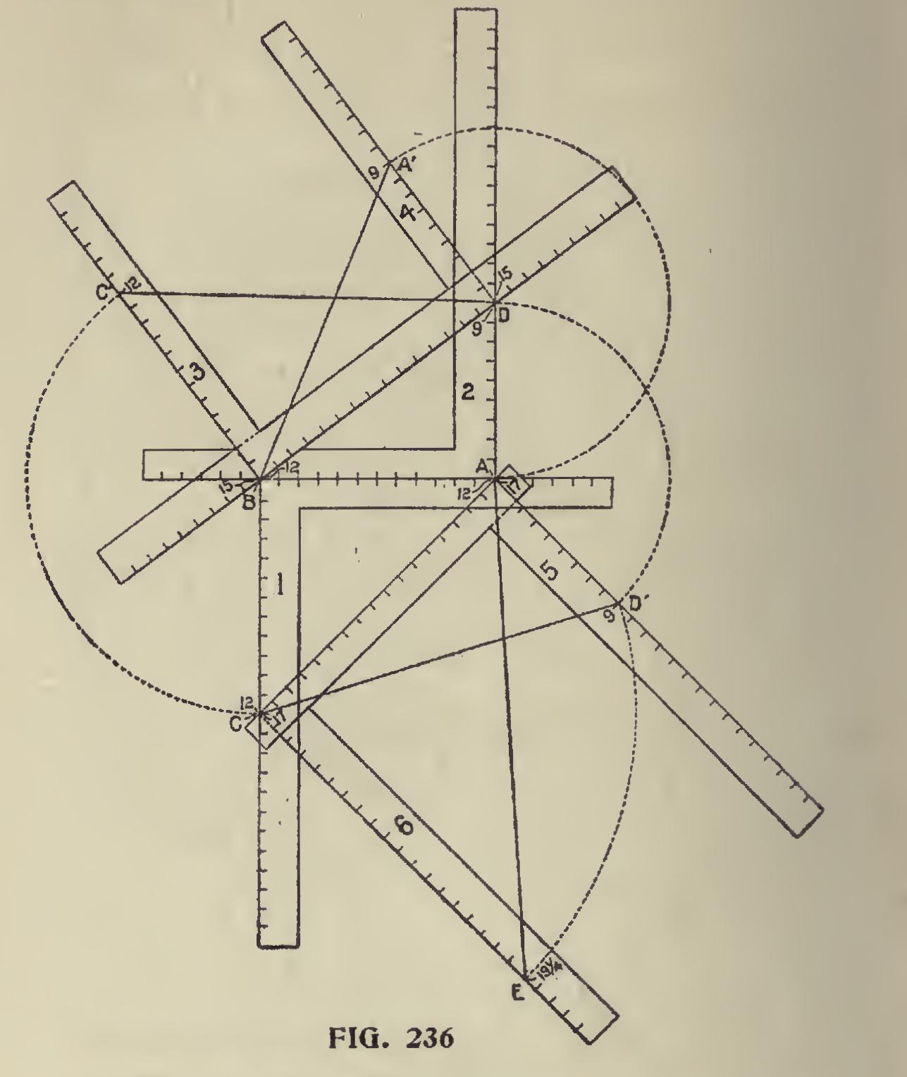
In Fig. 236 are shown all of the above angles formed by as many steel squares, with the cor responding numbers placed on same that help to form two of the sides of each angle, and, by refer ing to the preceding illustration, the reader can readily see how the cuts are obtained on the steel square.
Developing Cuts and Bevels.
Illustrating the cuts and bevels with the triangle is probably the most practical way of showing the various cuts contained in and about the roof, regardless of its shape or pitch given the rafters, as by its man ipulation all of the angles can be obtained. The steel square serves as the triangle, the blade and tongue forming two of the sides (run and rise) and these, applied to the pitch given the rafter, form the third side, or if it be for a miter, then the angle in degrees of same from the starting point from the surface cut will give the proper angle to obtain the cut.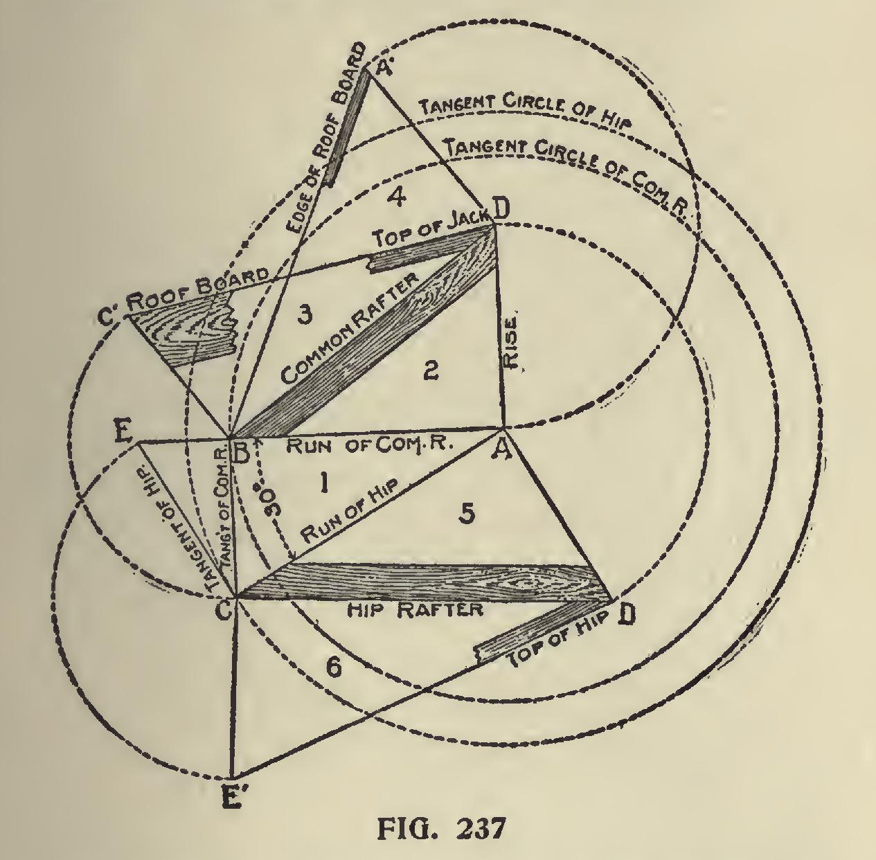
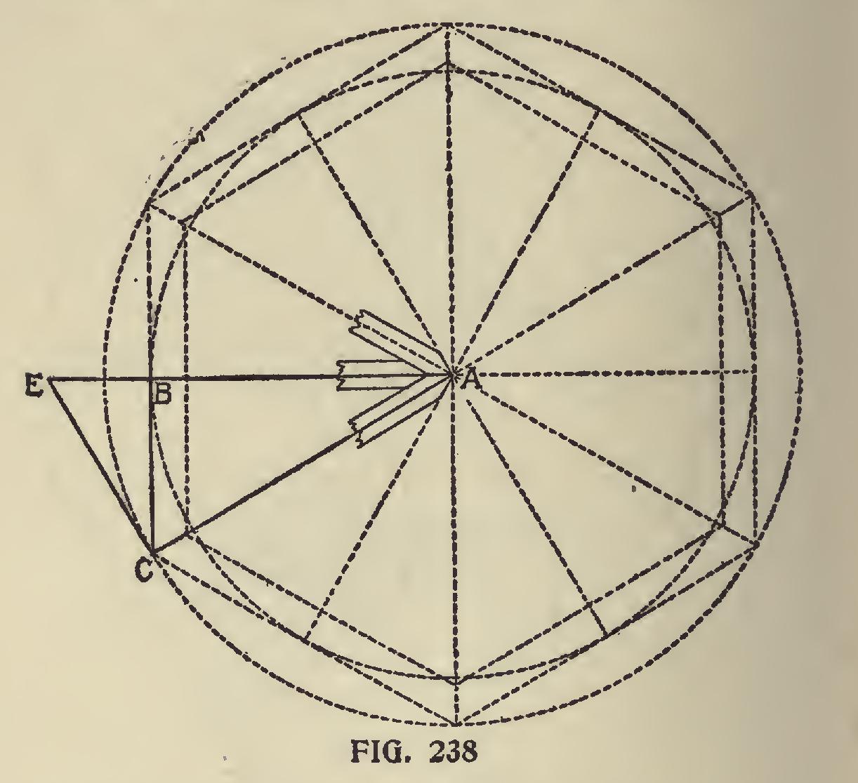
In Fig. 237 are shown the triangles for a hex agon (six sided) roof and by comparing with the preceding illustrations, the reader can see wherein they differ. The application is the same except in the sixth angle. Angle No. 1 represents the plan and governs the layout of the diagram. In this, the angle between the runs of the common rafter and the hip is at 30 degrees. Now, by referring to Fig. 238, we show the angle bounded by A-B-C as shown at No. 1 applied to the plan of the roof as follows : A-B run of the common rafter. A-C run of the hip. B-C tangent of the common rafter. Now by extending A-B intersecting a line at right angles from A-C as at E, then E-C will represent the length of the tangent from the hip. Note : See the difference in length when compared with the run of the hip.
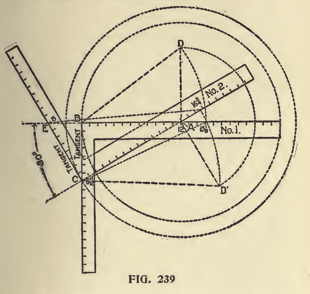
In Fig. 239 is shown how these angles may be
obtained with the aid of two steel squares. It may be worked to a scale of one inch to the foot, or full scale for a one-foot run of the common rafter, as shown in the illustration. The figure on the tongue that gives the hexagon miter (6 11-12) represents the tangent for the common rafter as shown on square No. 1, and by placing square No. 2 with its heel resting at 6 11-12 and with the blade intersecting at 12 on square No. 1, then a line continued from the heel of square No. 1 and in line with the blade intersecting the tongue of square No. 2, which in this case is at 8 and represents the tangent for the hip. Now by erecting the rise from the intersection of the blades to D and D', then B-D represents the length of the common rafter and D'-C that of the hip and these lengths, taken on the blade of the respective squares, will give the figures to use for the side cuts of the rafters. Thus-6 11-12 and 15 1-8 as shown, will give the side cut of the jack, or of the common rafter, to fit in the angle between the hips at the peak (see Fig. 238) and 8 and 16 3-4 will give the side cut of the unbacked hip to fit in the peak, or if it is first backed, then the same figures as shown on square No. 1 applied to the backing plane will give the same result. But, of course, this is not practical because the ends of the hip would run to a feather edge, as shown. A better way is to insert a hexagon block with sides equal the width of the hip, then the cut of th - hip would simply be the plumb cut. This would afford a better nailing space and each hip would hav, a direct bearing against the one on the opposite side.
Seat anu Plumi Cuts.
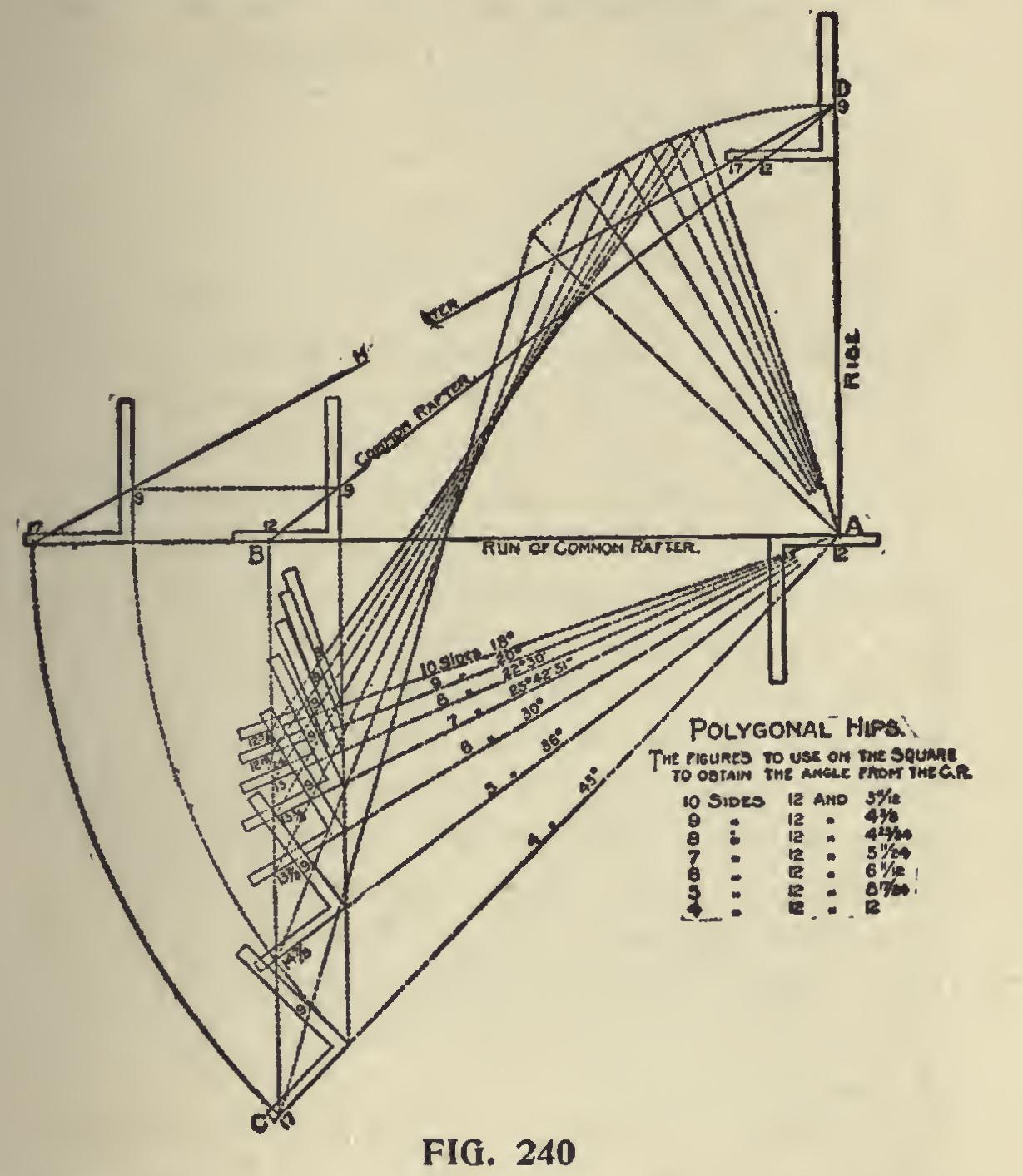
In Figs. 230 and 231 are illustrated the side cuts of polygonal jacks and tc complete this line of work, we show in Fig. 240 the accompanying illustration of the seat and plumb cuts for the corresponding hips and valleys. Beginning at horizontal line, which represents the run of the rafters, then 12 and 9 on the steel square represent the cuts for the common rafter for the 3-8 pitch. The steel square just beneath the horizontal line and with the 12-inch mark on the tongue resting at the rise, locates the angle of the respective runs with that of the common rafter and the figures to use on the blade of the square are the same as those used for the polygonal miters and as shown in the table. It will be seen, the vertical line dropping from 12 on the tongue of the steel square at the seat cut of the common rafter, as at B, and where the same intersects the figures on the tongue of the squares resting just beneath on the individual runs, gives the figures to use on that member for the cuts. The rise being the same as the common rafter, we use the same figures on the blade, as will be seen by referring to the illus tration. Now if the runs of the hip were pivoted at the point of the rise, as at A, and we could raise them up until they rest on the horizontal line, it would be found that the pitch lines would center at one point at the top, as at D, and they would all fall in between 12 and 17 on the tongue and center at 9 on the blade. The figures on the tongues of the squares would remain as shown for the seat cut. If there was no pitch given to these rafters, then the corresponding figures that give the polygonal miters would give the side cut of the hip, though the cuts on the square would be reversed,