Pitches and Roof Framing
rafter, run, hip, common, inches, tongue and rise
Fig. 210 illustrates a roof 25 feet wide and a rise 10 feet 9 inches, run 12 feet 6 inches. Measur ing across the square from 101 to 12i gives 16i, or 16 feet 6 inches is the length of rafter.

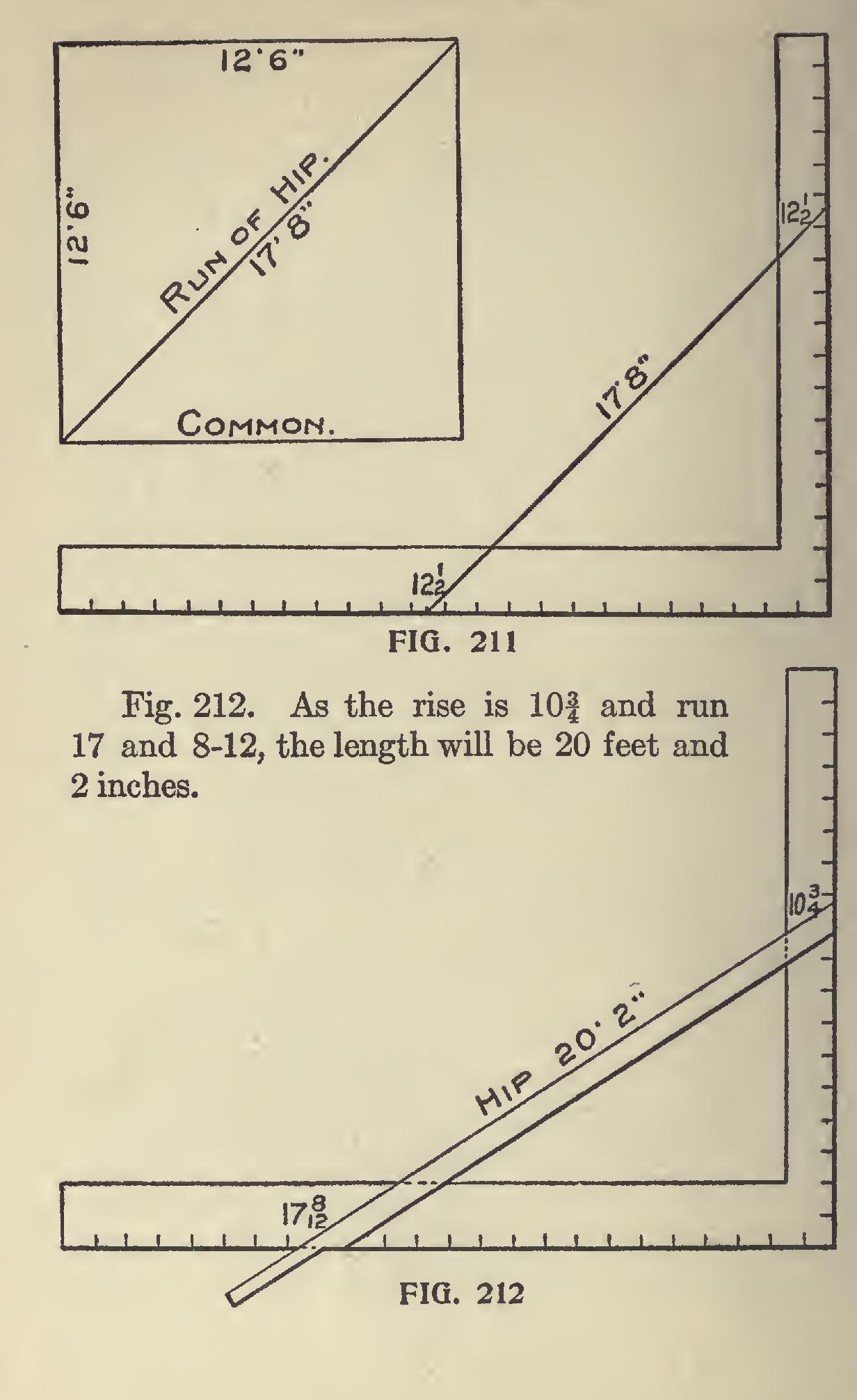
Fig. 211. If the run of common rafter is 12i, the run of the hip will be diagonal of 12i, which is 17 and 8-12, as is plainly illustrated.
Additions, Porches, etc.—Fig. 213. When a roof must go to a certain height to strike another building at a given point, as in additions, porches, etc., don't forget in getting the rise from plate to given point to allow the squaring up of heel as illustrated; and also remember to allow for ridge whenever one is used.
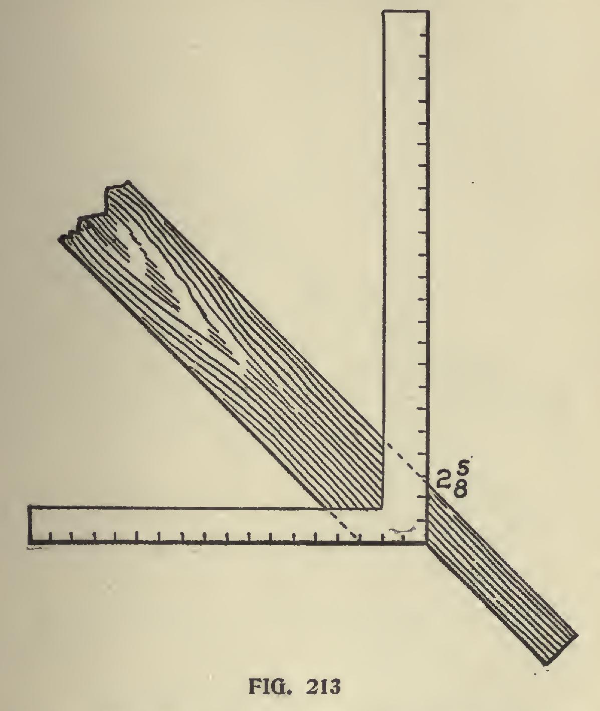
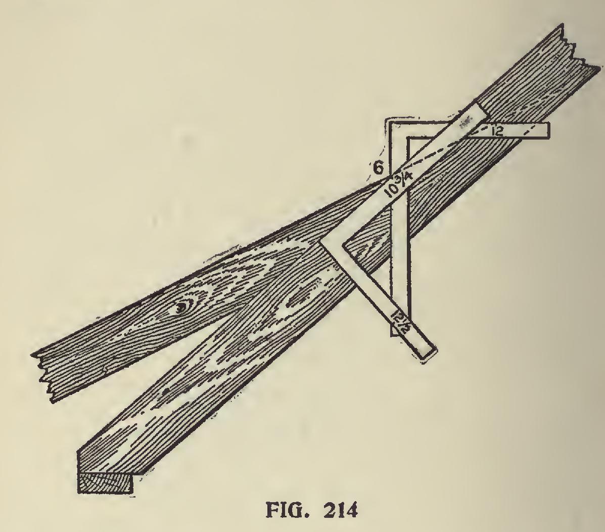
Fig. 214 illustrates the cut of top of quarter pitch rafter to lay on top of roof just mentioned. To apply square, first lay it on 12 and 6, which is quarter-pitch, and gives plumb-cut. From plumb cut lay off pitch of main roof 10 and 121, which gives cut.
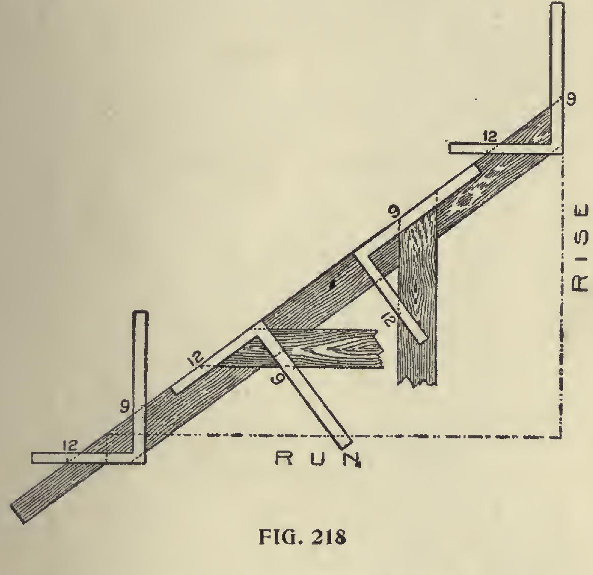
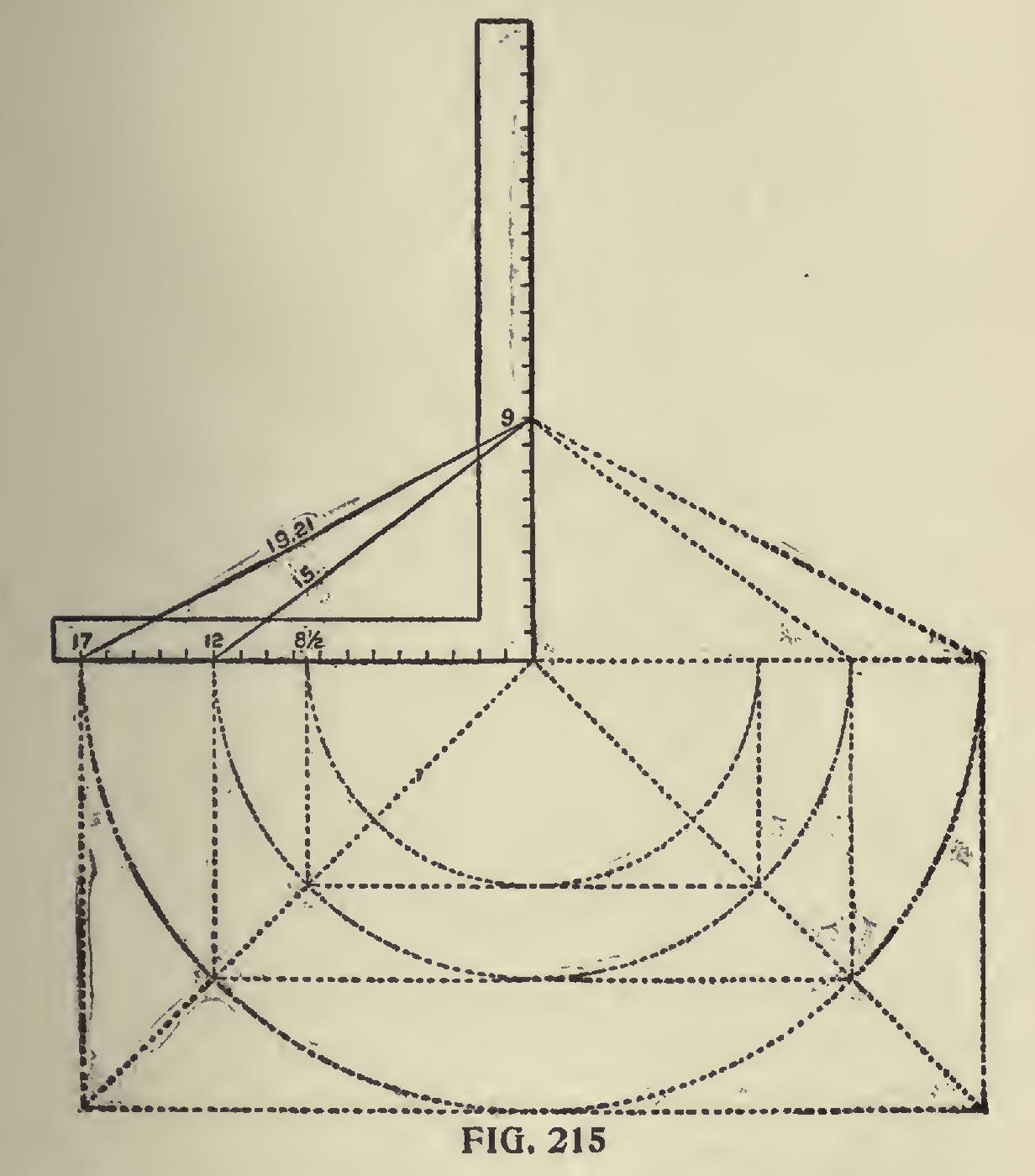
It is quite clear that a common rafter becomes a hip for a building of less span, as will be seen by referring to Fig. 215. Here the common rafter for a 12-inch run becomes a hip for an 81 inch run. A hip for a 12-inch run becomes a common rafter for a 17-inch run. Therefore, the same rule must ap ply to both, that is, the tangent (commonly called run) and rise, taken to scale on the square will give the seat and plumb cuts. The tangent and the length of the rafter taken to scale on the steel square will give the side cut for the hip to rest against the ridge tree. Cut on length. The same applies for the common rafter, which gives the side cut of the jack to rest against the hip or valley.
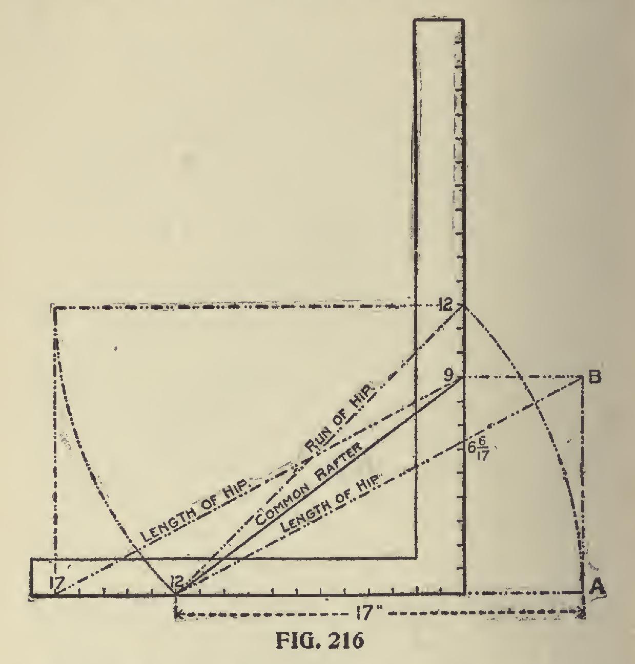
Taking the full scale for the hip as compared with the common rafter, it is practically 17 on the tongue and the length of the hip for a one-foot run of the gable taken on the blade, and the latter will give the cut. If 12 is used on the tongue for a foot run of the hip, its rise would necessarily be less than for the same run of the common rafter, as will be seen on Fig. 216. In this is shown the corresponding difference for the pitch. The diagonal line from 12 to 12 represents the length of the run of the hip, and this taken on a continued line of the run of the common rafter, as at "A," and erect the rise equal to that of the common rafter as at "B," and it will be seen a line from this to 12 on the tongue passes at 6 6-17 inches on the blade; because the common rafter having a rise of 9 inches to one foot, for one inch, it would only have 9-12 of an inch, while the hip would only have 9-17 of an inch to one inch. Then for 12 inches it
would be 12 times 9-17, equals 108-17,. or 6 6-17 inches. Therefore, 12 on the tongue and 6 6-17 on the blade will give the same result as 17 on the tongue and 9 on the blade, but as the former meth od necessitates a calculation that ends in fractions —fractions not given on the square—it is better to use the latter method because it obviates the fractions. In this illustration is also shown why 17 is used on the tongue, which is simply taking the length of the run of the hip on that member, as shown by the course of the dotted lines. A line from this point (17) to the rise of the common rafter, represents the length of the hip or valley for a one-foot run to correspond with that for the common rafter and is parallel with the line from 12 to "B," as in the former method. Thus 17 is a standard number on the tongue for the hip or val ley, just the same as 12 is used for the common rafter, the rise remaining the same avoids com putations and greatly simplifies the work. While 17 is used on the tongue to obtain the cuts, the ac tual measurement is a little less than 1-32 of an inch of being 17 inches. This, howelf er, is too small to consider, but the lengths of the rafters for accuracy should be reckoned from i'.97 inches.
In
the foregoing, we have tried to lead up more to the cause and effect and have in a general way touched on the different cuts about the roof, showing at the same time why they give correct results.
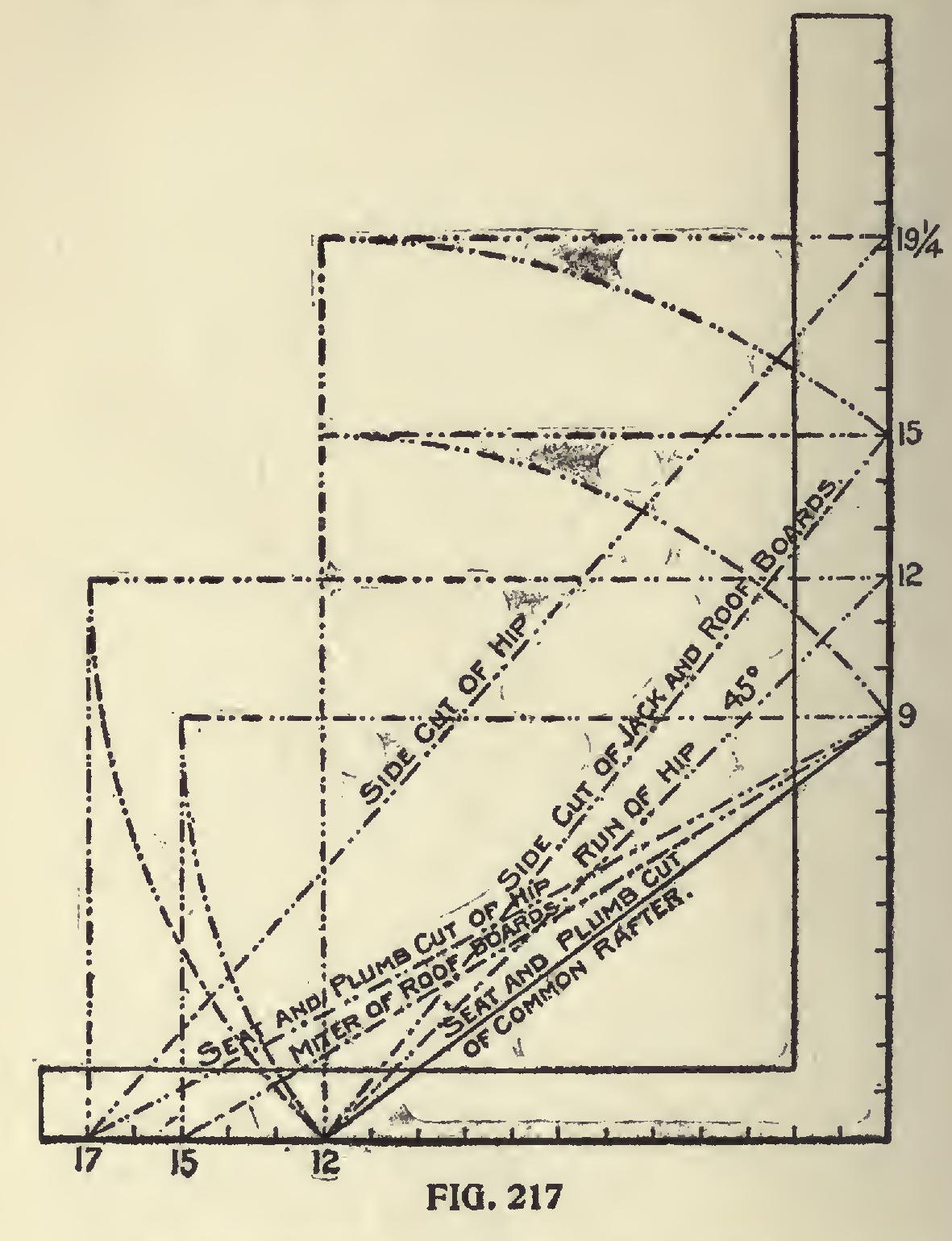
We will now take up the subject showing the various cuts in one diagram as shown in Fig. 217. Here are shown the measurements on the steel square.