Pitches and Roof Framing
cut, rafter, blade, square, plumb, fig, lines and figures
We have seen the carpenter, after cutting and setting the common rafters, climb up the gable and scribe the sheathing boards to the pitch of the rafter instead of using the same figures on the square that he used for the seat and plumb cuts of the common rafter, and yet, he too in his mind knew all about the square and how to frame a roof.
If the first man had possessed a knowledge of the tangents, he would have multiplied the inscribed diameter of the hexagon by 6.93 (6 11-12) and reduced to feet and inches, would have given the length of the sides and all of the cuts and bevels for the roof. The second man should have mul tiplied his diameter by 4.97 and reduced to feet and inches, would have given the length of the sides of his template. It is the knowledge of such things as these that counts in the race for success, and the day is fast approaching when he who would be successful in his trade must know the shortest and best methods.
Plumb Cut of Rafter.
In our rounds among the builders, we find that nine times out of ten the boss framer, after laying off the plumb cut on the rafter, would take a block cut from the rafter and place it edgewise along with the plumb cut and mark on the opposite side and then di agonally across the top of the rafter to the plumb line on the opposite side and then cut to these lines, which, of course, give correct results for either side cut of jack or hip for the square cornered building, but when asked to frame any other than for the square corner, more than likely could not explain and was, so to speak, up against it, because he did not understand the true principle. Yet what is true of the square corner is true of all other angles, which we think will be made clear by referring to Fig. 231. In this we show the angles for the polygons from 4 to 10 and are the same as those shown in Fig. 230, but the cuts are arrived at in a different way.
From this, it will be seen that it is the amount of the base of a triangle whose altitude is equal the thickness of the rafter, that is set off from the plumb cut. In the case of the square build ing, the base and altitude being equal is the reason that the thickness of the rafter set back from the plumb cut gives the proper angle across the top for the cut. In the illustration we show the amount to set off for the different polygonal jacks.
Octagon Jacks.—In Fig. 232 is shown the application for the octagon jack. The plumb lines A and B remain 4 10-12 inches apart, re gardless of the pitch given the common rafter, as will be seen by referring to the elevation in connection with this figure. Here we have the and the level or no pitch. These lines repre
sent the plumb cut on either side of the rafter and by cutting diagonally from one to the other across the back will fit to the side of the hip. It must be remembered that the thickness of the jack governs the width the lines will be apart. In Fig. 231 the jack is given as being full two inches thick. Hence, for the octagon they are 4 10-12 inches apart. But, after all, we do not get away from the use of the square, as will be seen by referring to the plan in Fig. 232. Here the square is shown applied to the back of the jack with the figures that give the octagon miter and the distance apart of the lines A and B is determined at the point where the blade inter sects edges of the rafter, and lines drawn at right angles from these points from the rafter govern the distance apart the plumb lines will be. For any other polygonal jack, proceed in like manner, using the figures on the square that give their miter. The result, however, will be the same as given in Fig. 230, which is much the better system, because it gives the cut direct from the square. However, the formula given in Fig. 231 is worth knowing.

Side Cut of Hip.
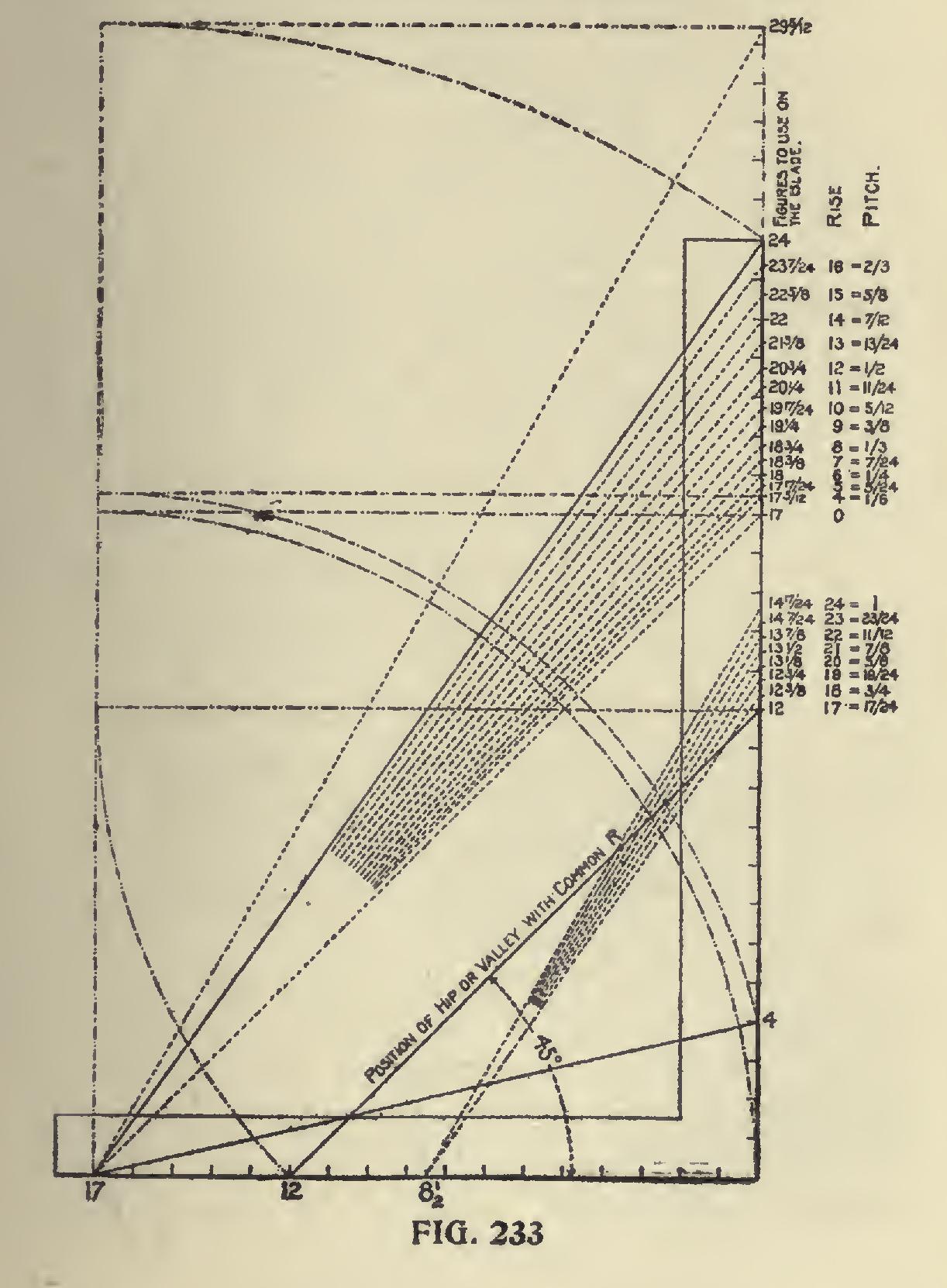
In Fig. 233 is shown the companion piece to Fig. 230, and represents the side cut of the hip. A line from 12 to 12 on the blade and tongue represents the run of the hip and its length taken on the tongue and the length of the hip (from 17 to the desired rise on the blade) taken on the blade, will give the correct angle across the top of the unbacked hip. The blade giving the cut.
The first column of figures to the right of the blade represents the length of the hips from a 4 to a 24-inch rise in comparison with the com mon rafter and are the figures to use on the blade to obtain the side cut. The second colunm represents the rise in inches to the foot run of the common rafter, and the third designates the pitch. Inasmuch as the lengths of the hip above the 16-inch rise exceed the length of the blade, it is necessary to reduce the scale. Therefore, the lines centering at 81 on the tongue are for the one half scale. The figures to use on the blade are, therefore, reduced in like proportion to what they would have been in the full scale. However, it must be understood that any figures on the blade and tongue may be used that are in proportion to those used in the full scale. Every fractional mark on the blade represents a scale. Therefore, taking the side of the square that is divided in twelfths there would be 24 x 12 = 288 different scales and all giving the same result, but the intersections on the tongue would be in compli cated fractions.