Pitches and Roof Framing
line, cut, seat, hip, rafter, twelfths and cuts
Measurement Line of All Jacks, Hips and Val= leys.—The true measurement line of all jacks, hips and valleys is at a line along the center of the back, and just where to place the square on the side of the rafter so as to make the cuts and length come right at that point is a question that taxes the skill of most carpenters, especially so in the case of the latter, where the same are to be backed.

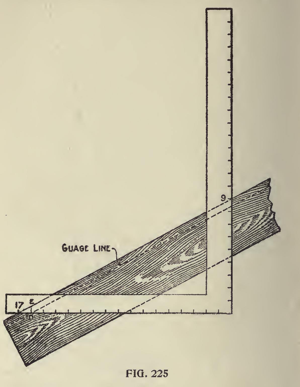
In Fig. 224 we show the hip and valley under different conditions for a square-cornered building. Beginning at the bottom is shown the plan of the rafter. The cross lines on same represent the angle of the plates for either hip or valley. Above the plan is shown the elevation. The sections 1-2-3-4 represent the position of the rafters under the fol lowing conditions: No. 1, hip when not backed; No. 2, hip when backed; No. 3, valley when not backed; No. 4, valley when backed. No. 1 is outlined by heavy lines and apparently sets lower than the others. By tracing the bottom line of the sections down to the seat of No. 1, thence up to the second elevation, will show just how far in the seat cut should be for each rafter. No. 1 cuts into the right-hand ver tical line above the plan, as at C, which would make it stand at the right height above the plate, at the outer edge of the rafter, but in order to make the seat cut clear the corner of plate, it is necessary to cut into the center line B. No. 2 cuts into the same point as No. 1 ,but owing to its being backed, the seat cut drops accordingly. No. 3, which is for the unbacked valley, also cuts into the center vertical line, and in order to clear the edges of the plate, must cut out at the sides to the left vertical line. No. 4 cuts in the same depth as the latter, but as much lower than Nos. 2 and 3 as they are below No. 1. The vertical lines "A" and "C" from the plan represent the width of the rafter. Therefore, if the rafter be two inches thick, the lines A-B-C would be one inch apart, and this amount set off along the seat cut, or a line parallel with it, will give the gauge point on the side of the rafter. To make this clearer, we refer to Fig.225. 17 and 9 give the seat cut. Now leaving the square rest as it is, measure back from 17 one-half the thickness of the rafter, which would locate the gauge point at 16, and this will be the point for the line from which to remove the wood back to the center line of the hip. The measurement from the
gauge point taken square out from the seat cut to the edge of the rafter as shown at D-E, shows how far apart the parallel lines of the seat cut will be under the above conditions. This rule applies to any pitch given the roof so long as the pitches are regular.
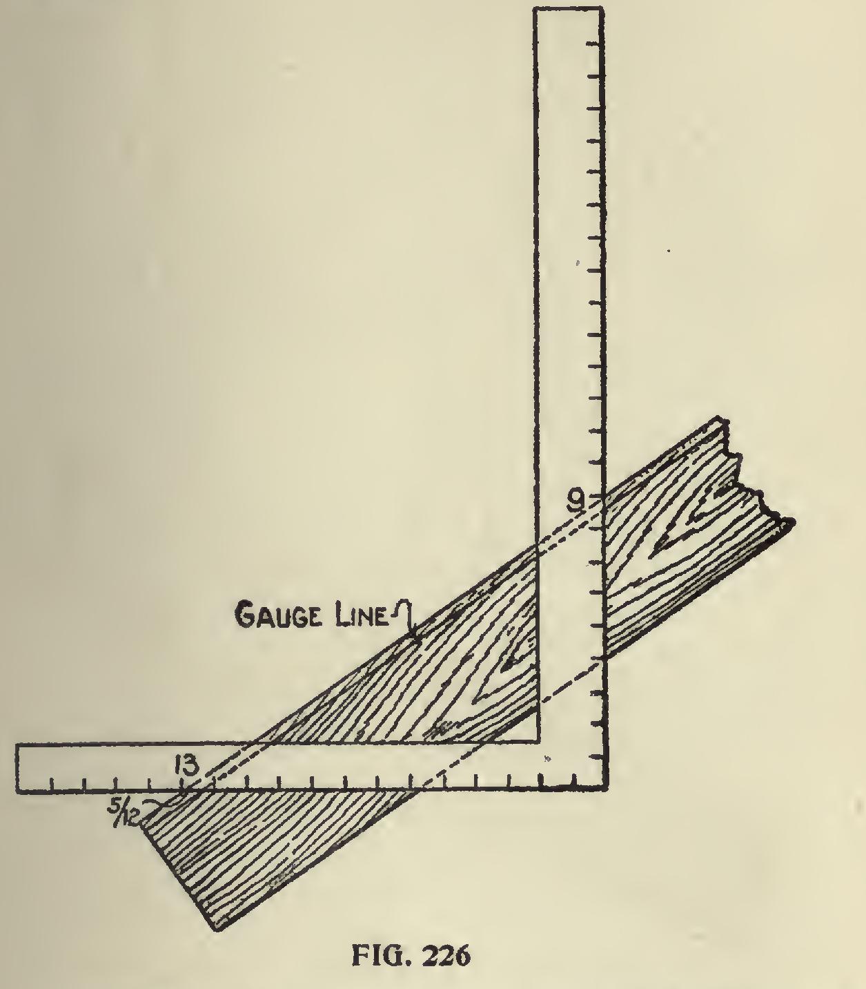
Backing Line for Octagon Hip.—We show in Fig. 226 the backing line for the octagon hip. From this, it will be seen, that the method is the same as that for the hip resting on a square cor ner, which is shown in Fig. 225. In this 17 and 9 give the seat and plumb cuts for the s pitch while 13 and 9 give the corresponding cuts for the octagon hip. In the former a point 12 twelfths or one inch, is taken back from the edge of the rafter along the seat cut for the gauge line, while in the latter, the point is taken 5 twelfths back. The backing for any other polygonal hip may be readily found in the same way by setting off the tangent for one-half the thickness of the hip. Thus for the hip resting on a square corner, the tangent is equal to one-half of the thickness. In other words, the amounts to set off are the same figures as those used to obtain the side cut for the corresponding jack (see the figures opposite the blade in Fig. 223), but consider them as so many twelfths of an inch. Thus it is 12 twelfths, or one inch, for the square-cornered building, 81 twelfths for the pentagon, 7 twelfths for the hexagon, 5 twelfths for the octagon. The figures to use for other polygonal roofs are shown in Fig. 223, but the reader must bear in mind that the fractional part of the number becomes only that part of a twelfth on an inch. Thus, for the octagon the number is 4 23-24, which is lacking only 1-24 of a twelfth of an inch of being 5 inches. This is so near being 5 that we call it 5 twelfths of an inch for the amount to set off on the seat cut line as before described and shown in Fig. 226.